OIL PUMP REMOVAL
CAUTION / NOTICE / HINT
Note
-
When replacing an injector (including interchanging injectors between cylinders) or common rail, replace the corresponding injection pipes with new ones.
-
w/ DPF
When fuel lines are disconnected, air may enter the fuel lines, leading to engine starting trouble. Therefore, perform forced regeneration and bleed the air from the fuel lines.
PROCEDURE
-
PRECAUTION
Note
After turning the engine switch off, waiting time may be required before disconnecting the cable from the battery terminal. Therefore, make sure to read the disconnecting the cable from the battery terminal notice before proceeding with work Click here.
-
DISCONNECT CABLE FROM NEGATIVE BATTERY TERMINAL
Note
When disconnecting the cable, some systems need to be initialized after the cable is reconnected Click here.
-
REMOVE ENGINE ASSEMBLY
-
REMOVE NO. 1 INTAKE AIR CONNECTOR PIPE
-
REMOVE GENERATOR ASSEMBLY
-
for 150A Type:
-
for 180A Type:
-
-
DISCONNECT NO. 1 OUTLET TURBO OIL HOSE
-
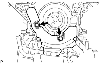
REMOVE NO. 1 ENGINE OIL LEVEL DIPSTICK GUIDE
-
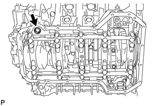
Remove the 2 bolts and No. 1 engine oil level dipstick guide.
-
-
DISCONNECT NO. 2 OUTLET TURBO OIL HOSE
-
DISCONNECT NO. 2 INLET TURBO OIL PIPE SUB-ASSEMBLY
-
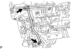
Remove the union bolt and gasket, and disconnect the No. 2 inlet turbo oil pipe sub-assembly.
-
-
REMOVE STIFFENER INSULATOR RH
-
Remove the 2 bolts and stiffener insulator RH.
-
-
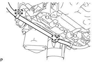
DISCONNECT NO. 1 OIL COOLER HOSE
-
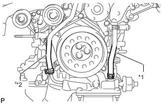
Text in Illustration *1 No. 1 Oil Cooler Hose *2 No. 2 Oil Cooler Hose Slide the hose clamp and disconnect the No. 1 oil cooler hose.
-
-
DISCONNECT NO. 2 OIL COOLER HOSE
-
Slide the hose clamp and disconnect the No. 2 oil cooler hose.
-
-
REMOVE V-RIBBED BELT TENSIONER ASSEMBLY
-
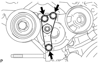
Remove the 3 bolts and V-ribbed belt tensioner bracket.
-
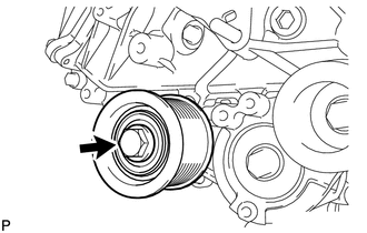
Remove the bolt and No. 1 idler pulley.
-

Remove the 5 bolts and V-ribbed belt tensioner assembly.
-
-
REMOVE CRANKSHAFT PULLEY
-
REMOVE TIMING GEAR COVER SPACER
-
Remove the 2 bolts and timing gear cover spacer.
-
-
REMOVE OIL FILTER ELEMENT
-
REMOVE OIL FILTER BRACKET SUB-ASSEMBLY
-
Disconnect the 2 wire harness clamps.
-
Remove the 3 bolts, 2 nuts and oil filter bracket sub-assembly.
-
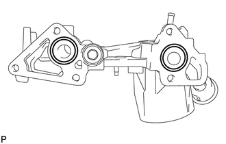
Remove the 2 O-rings from the oil filter bracket sub-assembly.
-
-
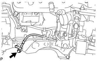
REMOVE ENGINE OIL LEVEL SENSOR
-
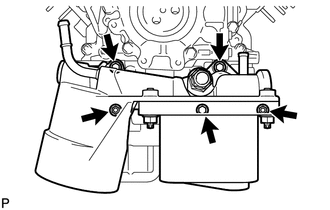
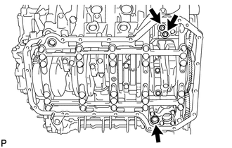
REMOVE NO. 2 OIL PAN SUB-ASSEMBLY
-
Remove the 10 bolts and 2 nuts.
-
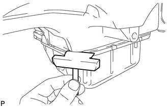
Insert the blade of an oil pan seal cutter between the oil pans. Cut through the applied sealer and remove the No. 2 oil pan sub-assembly.
Note
Be careful not to damage the contact surfaces of the No. 1 and No. 2 oil pans.
-
-
REMOVE OIL STRAINER SUB-ASSEMBLY
-
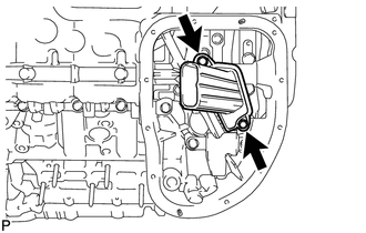
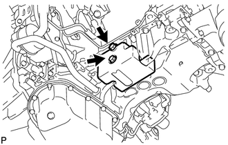
Remove the 2 bolts and oil strainer sub-assembly.
-
Remove the O-ring from the oil strainer sub-assembly.
-
-
REMOVE NO. 1 OIL PAN SUB-ASSEMBLY
-
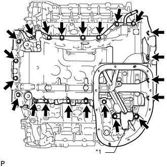
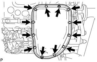
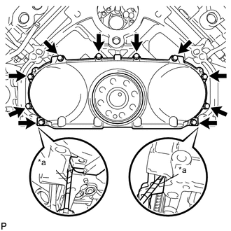
Text in Illustration *1 Oil Reflector Plate Remove the 20 bolts, 2 nuts and oil reflector plate.
Note
If the oil reflector plate is deformed, replace it.
Tech Tips
Be sure to clean the bolts and stud bolts, and check the threads for cracks or other damage.
-
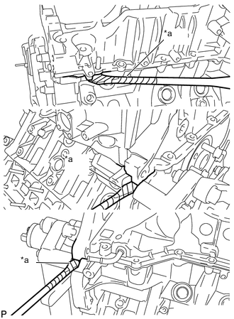
Text in Illustration *a Protective Tape Remove the No. 1 oil pan sub-assembly by prying between the No. 1 oil pan sub-assembly and cylinder block with a screwdriver.
Note
Be careful not to damage the contact surfaces of the cylinder block and No. 1 oil pan sub-assembly.
Tech Tips
Tape the screwdriver tip before use.
-
Remove the 3 O-rings.
-
Remove the cylinder block oil hole gasket.
-
-
REMOVE OIL REGULATOR ASSEMBLY
-
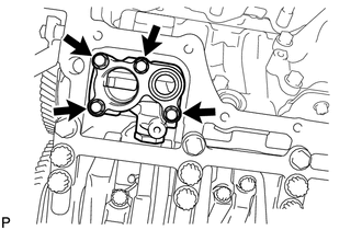
Remove the 4 bolts and oil regulator.
-
-
REMOVE REAR ENGINE OIL SEAL RETAINER
-
Text in Illustration *a Protective Tape Remove the 10 bolts.
-
Remove the rear engine oil seal retainer by prying between the oil seal retainer and cylinder block with a screwdriver.
Tech Tips
Tape the screwdriver tip before use.
-
-
REMOVE REAR CRANKSHAFT OIL SEAL
-
REMOVE OIL PUMP ASSEMBLY
-
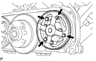
Remove the 4 bolts and oil pump assembly.
-