RADIATOR INSTALLATION
PROCEDURE
-
INSTALL RADIATOR ASSEMBLY
-
Install the radiator assembly with the 4 bolts.
- Torque:
- 18 N*m { 184 kgf*cm, 13 ft.*lbf }
-
-
INSTALL FAN PULLEY
-
INSTALL FAN SHROUD WITH FAN
-
INSTALL OIL COOLER TUBE
-
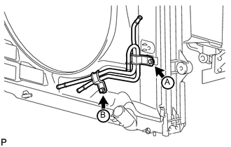
Temporarily install the oil cooler tube to the fan shroud with the bolt labeled A. Install the bolt labeled B. Then tighten the bolt labeled A to the specified torque.
- Torque:
- 5.0 N*m { 51 kgf*cm, 44 in.*lbf }
-
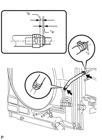
Text in Illustration *a 0 to 3.0 mm (0 to 0.118 in.) *b 2.0 to 7.0 mm (0.0785 to 0.275 in.) *c Paint Mark Install the inlet No. 4 oil cooler hose, and slide the 2 clips to secure the hose as shown in the illustration.
Note
Make sure the pinching portion of each clip is facing the direction shown in the illustration and the paint marks are aligned as shown in the illustration.
-
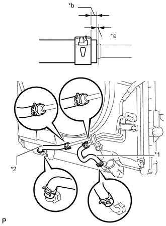
Text in Illustration *1 Inlet No. 2 Oil Cooler Hose *2 Inlet No. 3 Oil Cooler Hose *a 0 to 3.0 mm (0 to 0.118 in.) *b 2.0 to 7.0 mm (0.0785 to 0.275 in.) Install the inlet No. 2 oil cooler hose, and slide the 2 clips to secure the hose as shown in the illustration.
Note
Make sure the pinching portion of each clip is facing the direction shown in the illustration.
-
Install the inlet No. 3 oil cooler hose, and slide the 2 clips to secure the hose as shown in the illustration.
Note
Make sure the pinching portion of each clip is facing the direction shown in the illustration.
-
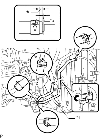
Text in Illustration *1 Outlet No. 1 Oil Cooler Hose *2 Inlet No. 1 Oil Cooler Hose *a 0 to 3.0 mm (0 to 0.118 in.) *b 2.0 to 7.0 mm (0.0785 to 0.275 in.) *c Paint Mark Install the outlet No. 1 oil cooler hose, and slide the 2 clips to secure the hose as shown in the illustration.
Note
Make sure the pinching portion of each clip is facing the direction shown in the illustration and the paint marks are aligned as shown in the illustration.
-
Attach the hose to the flexible hose clamp and close the clamp as shown in the illustration.
-
-
INSTALL V-RIBBED BELT
-
INSTALL NO. 3 IDLER PULLEY (w/ Viscous Heater)
-
INSTALL NO. 1 IDLER PULLEY (w/ Viscous Heater)
-
INSTALL V-RIBBED BELT (w/ Viscous Heater)
-
CONNECT NO. 2 RADIATOR HOSE
-
CONNECT NO. 1 RADIATOR HOSE
-
INSTALL RADIATOR RESERVOIR ASSEMBLY
-
INSTALL NO. 1 OIL RESERVOIR BRACKET
-
INSTALL VANE PUMP OIL RESERVOIR ASSEMBLY
-
INSTALL INTAKE AIR CONNECTOR
-
TEMPORARILY INSTALL NO. 1 AIR CLEANER HOSE
-
INSTALL AIR CLEANER CAP SUB-ASSEMBLY
-
INSTALL NO. 1 ENGINE COVER SUB-ASSEMBLY
-
INSTALL NO. 3 ENGINE ROOM WIRE
-
CONNECT CABLE TO NEGATIVE BATTERY TERMINAL
Note
When disconnecting the cable, some systems need to be initialized after the cable is reconnected Click here.
-
Connect the cables to negative (-) main battery and sub-battery terminals.
-
-
ADD ENGINE COOLANT
-
INSPECT FOR COOLANT LEAK
-
INSTALL RADIATOR SIDE DEFLECTOR LH
-
Install the radiator side deflector LH with the 4 clips.
-
-
INSTALL TRANSMISSION OIL COOLER AIR DUCT
-
INSTALL FRONT BUMPER COVER
-
INSTALL UPPER RADIATOR SUPPORT SEAL
-
INSTALL FRONT FENDER APRON SEAL FRONT RH
-
INSTALL NO. 1 ENGINE UNDER COVER SUB-ASSEMBLY
-
INSTALL FRONT FENDER SPLASH SHIELD SUB-ASSEMBLY RH
-
INSTALL FRONT FENDER SPLASH SHIELD SUB-ASSEMBLY LH