WATER PUMP REMOVAL
PROCEDURE
-
PRECAUTION
Note
After turning the engine switch off, waiting time may be required before disconnecting the cable from the battery terminal. Therefore, make sure to read the disconnecting the cable from the battery terminal notice before proceeding with work Click here.
-
DISCONNECT CABLE FROM NEGATIVE BATTERY TERMINAL
Note
When disconnecting the cable, some systems need to be initialized after the cable is reconnected Click here.
-
Disconnect the cables from the negative (-) main battery and sub-battery terminals.
-
-
REMOVE UPPER RADIATOR SUPPORT SEAL
-
REMOVE FRONT FENDER APRON SEAL FRONT RH
-
REMOVE FRONT FENDER SPLASH SHIELD SUB-ASSEMBLY LH
-
REMOVE FRONT FENDER SPLASH SHIELD SUB-ASSEMBLY RH
-
REMOVE NO. 1 ENGINE UNDER COVER SUB-ASSEMBLY
-
DRAIN ENGINE COOLANT
-
REMOVE NO. 3 ENGINE ROOM WIRE
-
REMOVE NO. 1 ENGINE COVER SUB-ASSEMBLY
-
REMOVE AIR CLEANER CAP SUB-ASSEMBLY
-
REMOVE NO. 1 AIR CLEANER HOSE
-
REMOVE INTAKE AIR CONNECTOR
-
REMOVE VANE PUMP OIL RESERVOIR ASSEMBLY
-
REMOVE NO. 1 OIL RESERVOIR BRACKET
-
REMOVE RADIATOR RESERVOIR ASSEMBLY
-
REMOVE VANE PUMP ASSEMBLY
-
DISCONNECT NO. 1 RADIATOR HOSE
-
DISCONNECT NO. 2 RADIATOR HOSE
-
REMOVE V-RIBBED BELT (w/ Viscous Heater)
-
REMOVE NO. 1 IDLER PULLEY (w/ Viscous Heater)
-
REMOVE NO. 3 IDLER PULLEY (w/ Viscous Heater)
-
REMOVE V-RIBBED BELT
-
REMOVE OIL COOLER TUBE
-
REMOVE FAN SHROUD WITH FAN
-
REMOVE FAN PULLEY
-
REMOVE HEATER WATER PIPE SUB-ASSEMBLY (w/ Viscous Heater)
-
REMOVE VISCOUS WITH MAGNET CLUTCH HEATER ASSEMBLY (w/ Viscous Heater)
-
REMOVE NO. 1 IDLER PULLEY BRACKET (w/ Viscous Heater)
-
REMOVE WATER INLET
-
REMOVE THERMOSTAT
-
REMOVE NO. 2 IDLER PULLEY (w/ Viscous Heater)
-
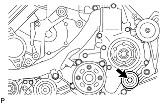
Remove the bolt, cover, No. 2 idler pulley and collar.
-
-
REMOVE NO. 2 IDLER PULLEY BRACKET (w/ Viscous Heater)
-
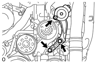
Remove the 3 bolts and No. 2 idler pulley bracket.
-
-
DISCONNECT NO. 1 OIL COOLER HOSE
-
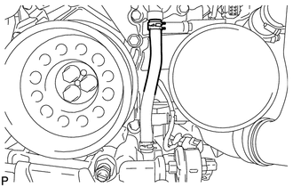
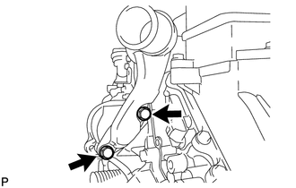
Slide the clip and disconnect the No. 1 oil cooler hose from the engine water pump assembly.
-
-
REMOVE FAN BRACKET SUB-ASSEMBLY
-
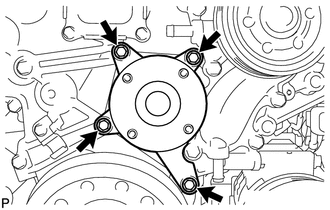
Remove the 4 bolts and fan bracket sub-assembly.
-
-
REMOVE WATER OUTLET
-
Disconnect the engine coolant temperature sensor connector.
-
Remove the 2 bolts, disconnect the water outlet from the No. 2 water hose joint, and remove the water outlet and gasket.
-
-
REMOVE ENGINE WATER PUMP ASSEMBLY
-
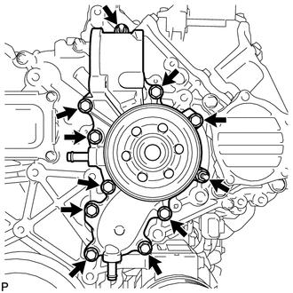
Remove the 9 bolts, 2 nuts, engine water pump assembly and gasket.
-