THERMOSTAT INSTALLATION
PROCEDURE
-
INSTALL WATER INLET SUB-ASSEMBLY WITH THERMOSTAT
-
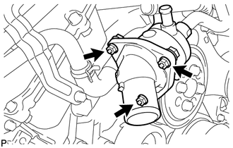
Install a new gasket and the water inlet with thermostat with the 3 nuts.
- Torque:
- 10 N*m { 102 kgf*cm, 7 ft.*lbf }
-

*1 RH Side *2 Front w/ Secondary Air Injection System:
Install the air tube bracket bolt.
- Torque:
- 10 N*m { 102 kgf*cm, 7 ft.*lbf }
-
Connect the No. 5 water by-pass hose.
Tech Tips
Install the hose so that the direction of the hose clamp is as indicated in the illustration.
-
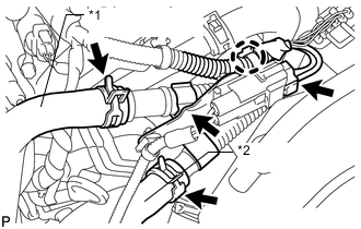
*1 No. 3 Air Hose *2 No. 2 Air Hose w/ Secondary Air Injection System:
-
Connect the air pump connector clamp holder.
-
Attach the wire harness clamp.
-
Connect the air pump connector.
-
Connect the No. 2 and No. 3 air hoses.
-
-
-
INSTALL FAN SHROUD
-
INSTALL NO. 2 RADIATOR HOSE
-
INSTALL NO. 1 RADIATOR HOSE
-
INSTALL AIR CLEANER ASSEMBLY
-
INSTALL AIR CLEANER HOSE ASSEMBLY
-
ADD ENGINE COOLANT
-
INSPECT FOR COOLANT LEAK
-
INSTALL UPPER RADIATOR SUPPORT SEAL
-
INSTALL V-BANK COVER SUB-ASSEMBLY
-
INSTALL NO. 1 ENGINE UNDER COVER SUB-ASSEMBLY
-
INSTALL FRONT FENDER SPLASH SHIELD SUB-ASSEMBLY LH
-
INSTALL FRONT FENDER SPLASH SHIELD SUB-ASSEMBLY RH