WATER PUMP INSTALLATION

PROCEDURE
-
INSTALL ENGINE WATER PUMP ASSEMBLY
-
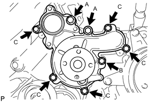
Install a new gasket and the engine water pump assembly with the 8 bolts shown in the illustration.
- Torque:
- for bolt A
- 47 N*m { 479 kgf*cm, 35 ft.*lbf }
- for bolt B
- 23 N*m { 235 kgf*cm, 17 ft.*lbf }
- for bolt C
- 20 N*m { 204 kgf*cm, 15 ft.*lbf }
Standard Bolt Item Length Thread Diameter Bolt A 80 mm (3.15 in.) 10 mm (0.394 in.) Bolt B 70 mm (2.76 in.) 8 mm (0.315 in.) Bolt C 25 mm (0.984 in.) 8 mm (0.315 in.)
-
-
INSTALL WATER PUMP PULLEY
-
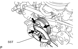
Temporarily install the pulley with the 4 bolts.
-
Using SST, hold the pulley and tighten the 4 bolts.
- SST
- 09960-10010 ( 09962-01000, 09963-01000 )
- Torque:
- 21 N*m { 214 kgf*cm, 15 ft.*lbf }
-
-
INSTALL WATER INLET HOUSING
-
Install a new gasket to the water pump.
-
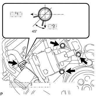
*1 RH Side *2 Front *3 No. 3 Water By-pass Hose Install the water inlet housing with the 3 bolts and connect the No. 3 water by-pass hose.
- Torque:
- 21 N*m { 214 kgf*cm, 15 ft.*lbf }
Tech Tips
Install the hose so that the direction of the hose clamp is as indicated in the illustration.
-

*1 RH Side *2 Front w/ Secondary Air Injection System:
Install the air tube bracket bolt.
- Torque:
- 10 N*m { 102 kgf*cm, 7 ft.*lbf }
-
Connect the No. 5 water by-pass hose.
Tech Tips
Install the hose so that the direction of the hose clamp is as indicated in the illustration.
-
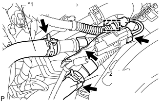
*1 No. 3 Air Hose *2 No. 2 Air Hose w/ Secondary Air Injection System:
-
Connect the air pump connector clamp holder.
-
Attach the wire harness clamp.
-
Connect the air pump connector.
-
Connect the No. 2 and No. 3 air hoses.
-
-
-
CONNECT NO. 2 WATER BY-PASS PIPE SUB-ASSEMBLY (w/ Oil Cooler)
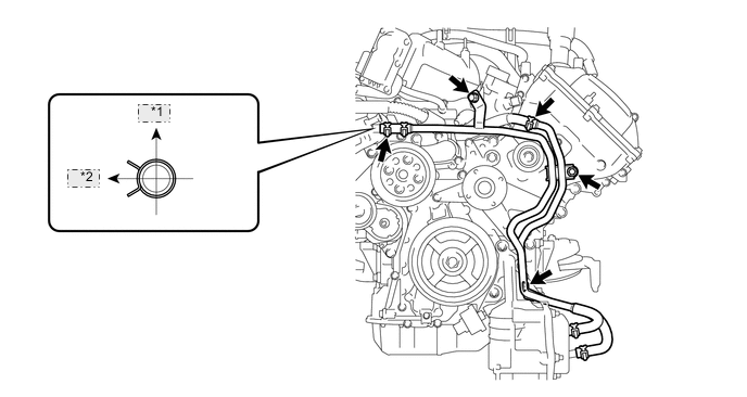
*1 Upper *2 Front
-
Connect the water by-pass pipe with water hose.
Tech Tips
Install the hose so that the direction of the hose clamp is as indicated in the illustration.
-
Install the 3 bolts.
- Torque:
- 10 N*m { 102 kgf*cm, 7 ft.*lbf }
-
Connect the No. 6 water by-pass hose.
-
-
INSTALL NO. 1 WATER BY-PASS HOSE
-
INSTALL FAN SHROUD
-
INSTALL NO. 1 RADIATOR HOSE
-
INSTALL NO. 2 RADIATOR HOSE
-
INSTALL AIR CLEANER ASSEMBLY
-
INSTALL AIR CLEANER HOSE ASSEMBLY
-
ADD ENGINE COOLANT
-
INSPECT FOR COOLANT LEAK
-
INSTALL UPPER RADIATOR SUPPORT SEAL
-
INSTALL V-BANK COVER SUB-ASSEMBLY
-
INSTALL NO. 1 ENGINE UNDER COVER SUB-ASSEMBLY
-
INSTALL FRONT FENDER SPLASH SHIELD SUB-ASSEMBLY LH
-
INSTALL FRONT FENDER SPLASH SHIELD SUB-ASSEMBLY RH