EXHAUST MANIFOLD W/ TURBOCHARGER INSPECTION
PROCEDURE
-
VISUALLY CHECK TURBOCHARGER SUB-ASSEMBLY
-
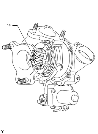
Text in Illustration *a Turbine Wheel Check for deformation and cracks in the turbine wheel on the exhaust side.
If the turbine wheel is cracked or deformed, replace the turbocharger sub-assembly.
-
-
INSPECT AXIAL PLAY OF TURBINE SHAFT
-
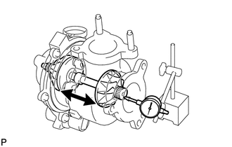
Using a dial indicator, insert the needle of the dial indicator into the exhaust side of the turbine shaft.
-
Move the turbine shaft in an axial direction and measure the axial play of the turbine shaft.
Maximum axial play 0.09 mm (0.00354 in.) Note
Make sure that the turbocharger sub-assembly and any dial indicators are securely fixed in place when performing measurements.
If the axial play is more than the maximum, replace the turbocharger sub-assembly.
-
-
INSPECT RADIAL PLAY OF TURBINE SHAFT
-
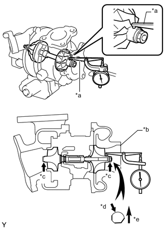
Text in Illustration *a Lever Probe *b Air Intake Side *c Lift Up *d Not Cut for Balancing *e Upward Connect a lever probe to a dial indicator.
-
Rotate the turbine shaft so that a part that has not been cut for shaft balancing is facing upwards on the air intake side.
-
Place the lever probe against the shaft at the position shown in the illustration.
-
Lift up both sides of the turbine shaft to move it in a radial direction and measure the radial play of the turbine shaft.
Maximum radial play 0.16 mm (0.00630 in.) If the radial play is more than the maximum, replace the turbocharger sub-assembly.
-
-
CHECK TURBINE SHAFT ROTATION
-
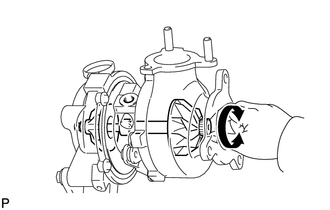
Rotate the turbine wheel on the exhaust side with your finger and check that it rotates smoothly.
Tech Tips
Even if it takes a little effort to rotate the turbine wheel, this is not a problem.
If the turbine wheel does not rotate smoothly, replace the turbocharger sub-assembly.
-
-
INSPECT EXHAUST MANIFOLD
-
Using a precision straightedge and feeler gauge, measure the warpage of the contact surface between the exhaust manifold and cylinder head sub-assembly.
Maximum warpage 0.80 mm (0.0315 in.) 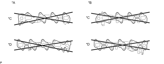
Text in Illustration *A w/ DPF *B w/o DPF *C for Bank 1 *D for Bank 2 If the warpage is more than the maximum, replace the exhaust manifold.
-