INTAKE MANIFOLD INSPECTION
PROCEDURE
-
INSPECT INTAKE MANIFOLD FOR FLATNESS
-
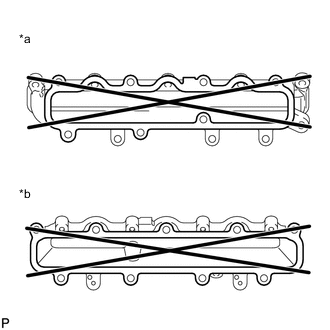
Text in Illustration *a No. 3 Intake Manifold Side *b Cylinder Head Sub-assembly Side Using a precision straightedge and feeler gauge, measure the warpage of the contact surface between the intake manifold and No. 3 intake manifold, and the intake manifold and cylinder head sub-assembly.
Maximum Warpage Item Specified Condition No. 3 intake manifold 0.10 mm (0.00394 in.) Cylinder head sub-assembly 0.10 mm (0.00394 in.) If the warpage is more than the maximum, replace the intake manifold.
-
-
INSPECT NO. 2 INTAKE MANIFOLD FOR FLATNESS
-
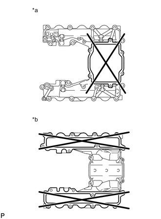
Text in Illustration *a No. 3 Intake Manifold Side *b Cylinder Head Sub-assembly Side Using a precision straightedge and feeler gauge, measure the warpage of the contact surface between the No. 2 intake manifold and No. 3 intake manifold, and the No. 2 intake manifold and cylinder head sub-assembly.
Maximum Warpage Item Specified Condition No. 3 intake manifold 0.10 mm (0.00394 in.) Cylinder head sub-assembly 0.10 mm (0.00394 in.) If the warpage is more than the maximum, replace the No. 2 intake manifold.
-
-
INSPECT NO. 3 INTAKE MANIFOLD FOR FLATNESS
-
Text in Illustration *a Intake Pipe Side *b Intake Manifold Side Using a precision straightedge and feeler gauge, measure the warpage of the contact surface between the No. 3 intake manifold and intake manifold, the No. 3 intake manifold and No. 2 intake manifold, and the No. 3 intake manifold and intake pipe.
Maximum Warpage Item Specified Condition Intake pipe 0.10 mm (0.00394 in.) Intake manifold and No. 3 intake manifold 0.15 mm (0.00591 in.) No. 2 intake manifold and No. 3 intake manifold 0.15 mm (0.00591 in.) If the warpage is more than the maximum, replace the No. 3 intake manifold.
-