INTAKE SYSTEM SYSTEM DIAGRAM

-
TURBOCHARGER SYSTEM ILLUSTRATION
-
The turbocharger system is comprised of the Variable Nozzle (VN) type turbocharger sub-assembly and ECM.
-
The turbocharger sub-assembly has a nozzle vane which opens and closes to control the volume of the exhaust gas flowing into the turbine. This, in turn, controls the boost pressure. When the nozzle vane moves towards the closing direction, the pressure increases. When the vane moves towards the opening direction, the pressure decreases.
-
The turbocharger sub-assembly actuator built onto the compressor housing side actuates the nozzle vane. The nozzle vane position sensor built onto the actuator detects the opening angle of the nozzle vane. The ECM receives a nozzle vane position sensor signal. Based on this signal, the ECM operates the DC motor and controls the nozzle vane opening angle.
-
The ECM controls the nozzle vane position according to the driving conditions in order to create the optimal pressure.
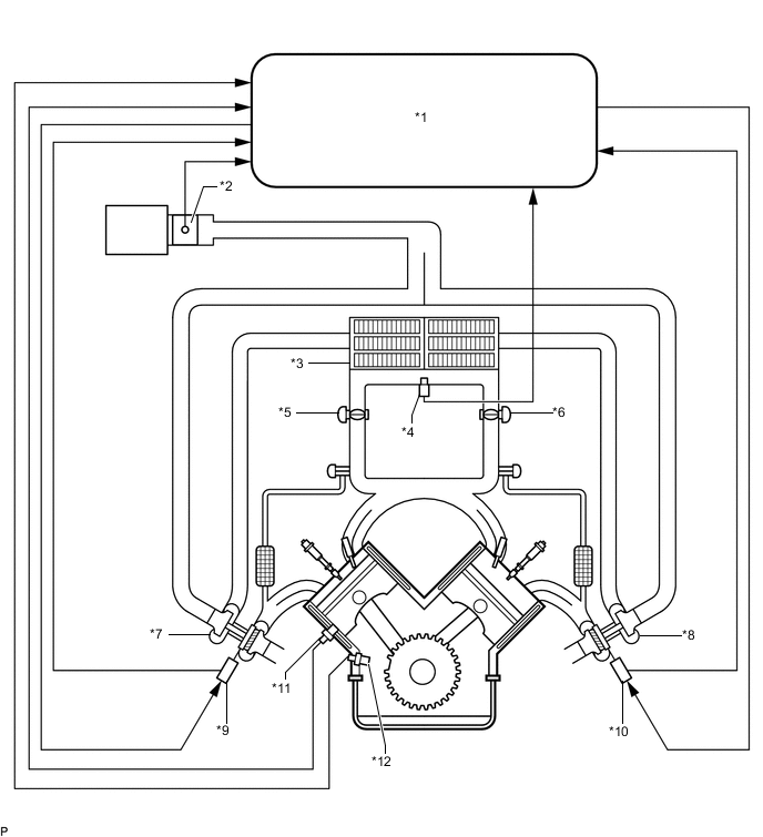
Text in Illustration *1 ECM *2 Mass Air Flow Meter Sub-assembly *3 Intercooler Assembly *4 Manifold Absolute Pressure Sensor *5 Diesel Throttle Body Assembly RH (for Bank 1) *6 Diesel Throttle Body Assembly LH (for Bank 2) *7 Turbocharger Sub-assembly (for Bank 1) *8 No. 2 Turbocharger Sub-assembly (for Bank 2) *9 DC Motor (for Bank 1) *10 DC Motor (for Bank 2) *11 Engine Coolant Temperature Sensor *12 Crankshaft Position Sensor
-
-
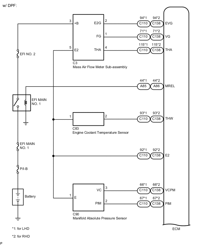
INTAKE SYSTEM WIRING DIAGRAM
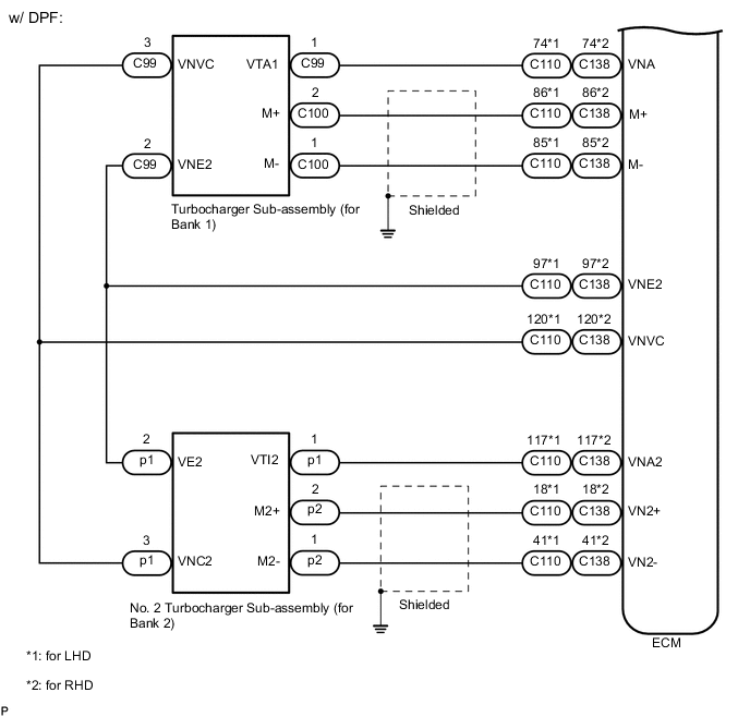
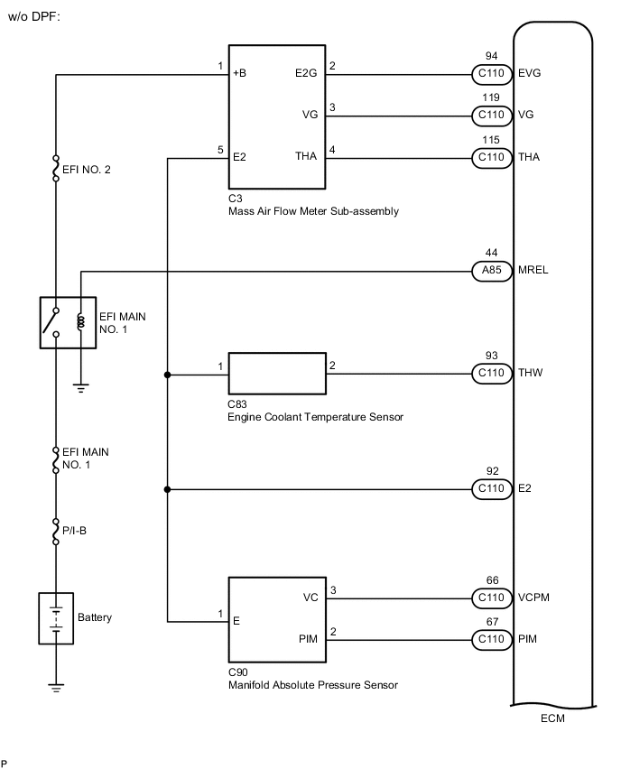
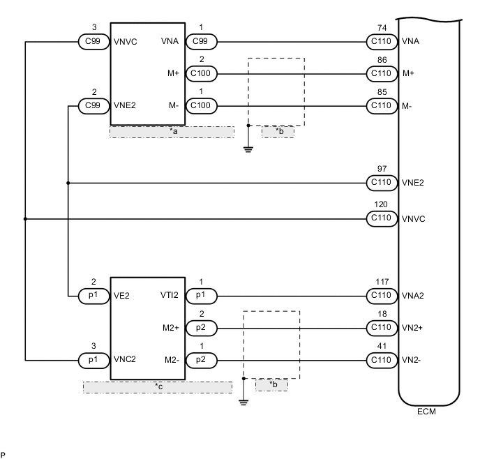
w/o DPF *a Turbocharger Sub-assembly (for Bank 1) *b Shielded *c No. 2 Turbocharger Sub-assembly (for Bank 2)