EXHAUST PIPE(w/ DPF) INSTALLATION
CAUTION / NOTICE / HINT
CAUTION:
-
Wear protective gloves and protective glasses when installing the exhaust pipe assembly.
-
The exhaust pipe assembly is extremely hot immediately after the engine has stopped.
-
Confirm that the exhaust pipe assembly has cooled down before removing it.
PROCEDURE
-
INSTALL EXHAUST GAS TEMPERATURE SENSOR
-
INSTALL NO. 2 EXHAUST GAS TEMPERATURE SENSOR
-
INSTALL NO. 3 EXHAUST GAS TEMPERATURE SENSOR
-
INSTALL MONOLITHIC CONVERTER ASSEMBLY LH
-
Install a new gasket to the No. 2 turbocharger sub-assembly.
Tech Tips
Make sure that the claw of the gasket faces downward.
-
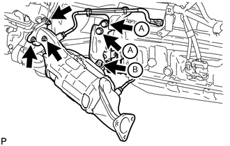
Install the monolithic converter assembly LH to the No. 2 turbocharger sub-assembly with 3 new nuts.
- Torque:
- 47 N*m { 479 kgf*cm, 35 ft.*lbf }
-
Temporarily install the No. 2 manifold stay to the transmission assembly with the 3 bolts.
-
Tighten the 2 bolts labeled A in the illustration first, and then tighten the bolt labeled B in the illustration.
- Torque:
- 43 N*m { 438 kgf*cm, 32 ft.*lbf }
-
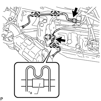
Text in Illustration *a Tape Attach the 4 clamps and connect the 2 exhaust gas temperature sensor connectors.
Tech Tips
Make sure that the tape is in the position shown in the illustration.
-
-
INSTALL FRONT PROPELLER SHAFT ASSEMBLY
-
INSTALL MONOLITHIC CONVERTER ASSEMBLY
-
Install a new gasket to the turbocharger sub-assembly.
Tech Tips
Make sure that the claw of the gasket faces the transmission assembly.
-
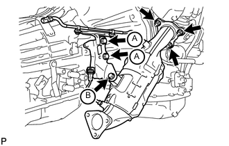
Install the monolithic converter assembly to the turbocharger sub-assembly with 3 new nuts.
- Torque:
- 47 N*m { 479 kgf*cm, 35 ft.*lbf }
-
Temporarily install the manifold stay to the transmission assembly with the 3 bolts.
-
Tighten the 2 bolts labeled A in the illustration first, and then tighten the bolt labeled B in the illustration.
- Torque:
- 43 N*m { 438 kgf*cm, 32 ft.*lbf }
-
Attach the 4 clamps and connect the 2 exhaust gas temperature sensor connectors.
-
-
INSTALL NO. 4 EXHAUST GAS TEMPERATURE SENSOR
-
INSTALL FRONT NO. 2 EXHAUST PIPE ASSEMBLY
-
Install a new gasket and the front No. 2 exhaust pipe assembly to the monolithic converter assembly LH with 3 new nuts.
- Torque:
- 48 N*m { 489 kgf*cm, 35 ft.*lbf }
-
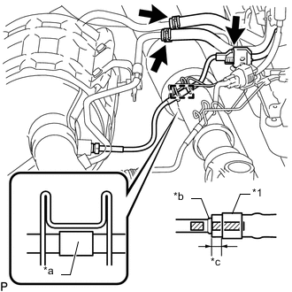
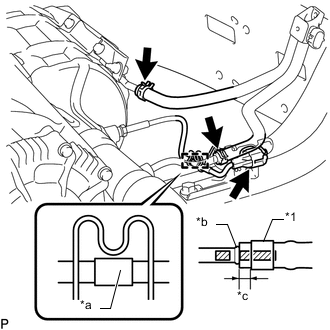
Text in Illustration *1 Clip *a Tape *b Stopper *c 2.0 to 7.0 mm (0.0787 to 0.276 in.) 
Paint Mark Attach the clamp and connect the exhaust gas temperature sensor connector.
Tech Tips
Make sure that the tape is in the position shown in the illustration.
-
Install 2 new clips to the 2 air hoses.
-
Connect the 2 air hoses to the front No. 2 exhaust pipe assembly, and slide the 2 clips to secure the hose.
Note
-
Align the paint marks of the front No. 2 exhaust pipe assembly and air hose and push on the air hose until it contacts the stopper.
-
Make sure the clip is 4.0 to 10 mm (0.157 to 0.394 in.) from the end of the air hose when installing the clip.
-
Make sure that there is no slack in the air hose, and that it is not twisted or bent.
-
Take care not to damage the inner or outer surface of the air hose when installing it. If the air hose is damaged, replace it with a new one.
-
-
-
INSTALL NO. 5 EXHAUST PIPE ASSEMBLY
-
Install a new gasket and the No. 5 exhaust pipe assembly to the front No. 2 exhaust pipe assembly with 2 new nuts.
- Torque:
- 48 N*m { 489 kgf*cm, 35 ft.*lbf }
-
-
INSTALL FRONT EXHAUST PIPE ASSEMBLY
-
Install a new gasket and the front exhaust pipe assembly to the monolithic converter assembly with 3 new nuts.
- Torque:
- 48 N*m { 489 kgf*cm, 35 ft.*lbf }
-
Text in Illustration *1 Clip *a Tape *b Stopper *c 2.0 to 7.0 mm (0.0787 to 0.276 in.) Paint Mark Attach the clamp and connect the exhaust gas temperature sensor connector.
Tech Tips
Make sure that the tape is in the position shown in the illustration.
-
Install 2 new clips to the 2 air hoses.
-
Connect the 2 air hoses to the front exhaust pipe assembly, and slide the 2 clips to secure the hose.
Note
-
Align the paint marks of the front exhaust pipe assembly and air hose and push on the air hose until it contacts the stopper.
-
Make sure the clip is 4.0 to 10 mm (0.157 to 0.394 in.) from the end of the air hose when installing the clip.
-
Make sure that there is no slack in the air hose, and that it is not twisted or bent.
-
Take care not to damage the inner or outer surface of the air hose when installing it. If the air hose is damaged, replace it with a new one.
-
-
-
INSTALL OIL PAN PROTECTOR ASSEMBLY RH
-
INSTALL OIL PAN PROTECTOR ASSEMBLY LH
-
INSTALL CENTER EXHAUST PIPE ASSEMBLY
-
Check the free length.
-
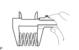
Using a vernier caliper, measure the free length of the compression spring.
Free length 43 mm (1.69 in.) If the free length is less than the minimum, replace the compression spring.
-
-
Connect the center exhaust pipe assembly to the 3 exhaust pipe supports.
-
Install 2 new gaskets to the No. 5 exhaust pipe assembly and front exhaust pipe assembly.
-
Install the center exhaust pipe assembly to the No. 5 exhaust pipe assembly and front exhaust pipe assembly with the 4 bolts and 2 compression springs.
- Torque:
- for center exhaust pipe assembly and front exhaust pipe assembly
- 43 N*m { 438 kgf*cm, 32 ft.*lbf }
- for center exhaust pipe assembly and No. 5 exhaust pipe assembly
- 48 N*m { 489 kgf*cm, 35 ft.*lbf }
-
-
INSTALL TAILPIPE ASSEMBLY
-
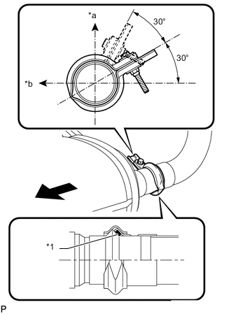
Text in Illustration *1 Gasket *a Top *b LH Side 
Front Connect the tailpipe assembly to the 2 exhaust pipe supports.
-
Install a new gasket to the center exhaust pipe assembly.
-
Connect the tailpipe assembly to the center exhaust pipe assembly with a new clamp.
Tech Tips
Install the clamp within the angle range shown in the illustration.
-
Tighten the bolt.
- Torque:
- 32 N*m { 326 kgf*cm, 24 ft.*lbf }
-
-
INSTALL AIR FUEL RATIO SENSOR
-
INSPECT FOR EXHAUST GAS LEAK
-
INSTALL NO. 2 ENGINE UNDER COVER
-
Install the No. 2 engine under cover to the frame with the 6 bolts.
- Torque:
- 29 N*m { 296 kgf*cm, 21 ft.*lbf }
-
-
INSTALL FRONT FENDER APRON SEAL REAR LH
-
Install the front fender apron seal rear LH with the 4 clips.
-
-
INSTALL FRONT FENDER APRON SEAL REAR RH
-
Install the front fender apron seal rear RH with the 4 clips.
-
-
PERFORM CATALYST RECORD OF DPF THERMAL DETERIORATION CLEAR FUNCTION