EXHAUST FUEL ADDITION INJECTOR(for DPF) INSTALLATION
CAUTION / NOTICE / HINT
Note
-
When replacing an injector (including interchanging injectors between cylinders) or common rail, replace the corresponding injection pipes with new ones.
-
When fuel lines are disconnected, air may enter the fuel lines, leading to engine starting trouble. Therefore, perform forced regeneration and bleed the air from the fuel lines Click here.
PROCEDURE
-
INSTALL FUEL INJECTOR SEAL
-
Install 2 new fuel injector seals.
-
-
INSTALL EXHAUST FUEL ADDITION INJECTOR ASSEMBLY
Note
If there is foreign matter on the installation surface of the exhaust fuel addition injector, be sure to clean it before installation.
-
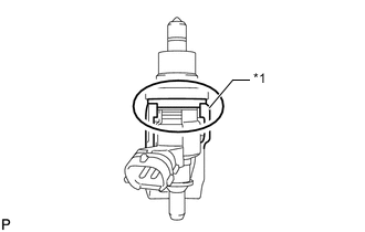
Text in Illustration *1 Nozzle Holder Clamp Install 2 new gaskets, the 2 exhaust fuel addition injectors, 2 nozzle holder clamps and 2 new washers with the 2 bolts.
- Torque:
- 28 N*m { 286 kgf*cm, 21 ft.*lbf }
Tech Tips
Align the nozzle holder clamp with the cutouts of the injector as shown in the illustration.
-
-
CONNECT FUEL TUBE SUB-ASSEMBLY
-
Connect the 2 fuel tube connectors to the exhaust fuel addition injector.
-
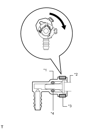
Text in Illustration *1 Fuel Tube Connector *2 Exhaust Fuel Addition Injector *3 Retainer *4 O-Ring Turn the 2 retainers in the direction indicated by the arrow until they make a "click" sound.
Note
-
If the fuel tube connector is not inserted to the correct position on the injector, the retainer cannot be turned far enough in the direction of the arrow.
-
Before connecting the fuel tube connector and fuel pipe, check that there is no damage or foreign matter on the connecting part of the fuel pipe.
-
After connecting the fuel tube connector and fuel pipe, check that they are securely connected by trying to pull them apart.
-
-
-
INSTALL NO. 1 FUEL INJECTOR PROTECTOR
-
INSTALL CYLINDER HEAD COVER SILENCER RH
-
INSTALL NO. 2 FUEL INJECTOR PROTECTOR
-
INSTALL CYLINDER HEAD COVER SILENCER LH
-
INSTALL NO. 1 VACUUM TRANSMITTING PIPE SUB-ASSEMBLY
-
INSTALL NO. 1 VACUUM SWITCHING VALVE ASSEMBLY
-
CONNECT ENGINE WIRE
-
INSTALL NO. 3 WATER BY-PASS PIPE (w/o Viscous Heater)
-
CONNECT FUEL HOSE
-
INSTALL NO. 1 AIR CLEANER PIPE SUB-ASSEMBLY
-
INSTALL HEATER WATER PIPE SUB-ASSEMBLY (w/ Viscous Heater)
-
INSTALL NO. 2 AIR CLEANER PIPE SUB-ASSEMBLY
-
INSTALL NO. 4 AIR TUBE
-
INSTALL NO. 2 AIR HOSE
-
INSTALL NO. 3 AIR TUBE
-
INSTALL NO. 1 AIR HOSE
-
INSTALL INTAKE AIR CONNECTOR
-
TEMPORARILY INSTALL NO. 1 AIR CLEANER HOSE
-
INSTALL AIR CLEANER CAP SUB-ASSEMBLY
-
INSTALL DIESEL THROTTLE BODY ASSEMBLY LH
-
INSTALL NO. 3 INTERCOOLER SUPPORT BRACKET
-
INSTALL NO. 1 GAS FILTER
-
INSTALL AIR TUBE SUB-ASSEMBLY LH
-
INSTALL DIESEL THROTTLE BODY ASSEMBLY RH
-
INSTALL AIR TUBE SUB-ASSEMBLY RH
-
INSTALL NO. 2 ENGINE OIL LEVEL DIPSTICK GUIDE
-
CONNECT WATER HOSE SUB-ASSEMBLY
-
INSTALL INTERCOOLER ASSEMBLY
-
CONNECT CABLE TO NEGATIVE BATTERY TERMINAL
Note
When disconnecting the cable, some systems need to be initialized after the cable is reconnected Click here.
-
Connect the cables to the negative (-) main battery and sub-battery terminals.
-
-
ADD ENGINE COOLANT
-
BLEED AIR FROM FUEL SYSTEM
-
PERFORM DPF FORCIBLE REGENERATION PROCEDURE
-
INSPECT FOR COOLANT LEAK
-
INSPECT FOR FUEL LEAK
-
INSPECT FOR OIL LEAK
-
INSTALL UPPER RADIATOR SUPPORT SEAL
-
INSTALL NO. 1 ENGINE UNDER COVER SUB-ASSEMBLY
-
INSTALL FRONT FENDER SPLASH SHIELD SUB-ASSEMBLY RH
-
INSTALL FRONT FENDER SPLASH SHIELD SUB-ASSEMBLY LH