EXHAUST MANIFOLD INSTALLATION
PROCEDURE
-
INSTALL AIR FUEL RATIO SENSOR (for Bank 2 Sensor 1)
-
INSTALL AIR FUEL RATIO SENSOR (for Bank 1 Sensor 1)
-
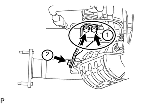
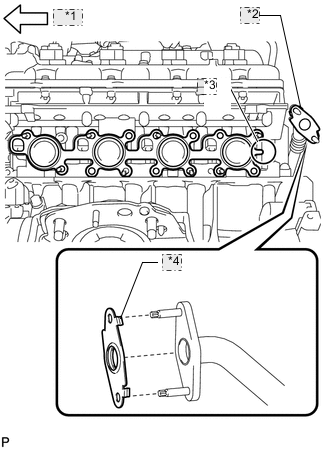
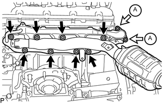
INSTALL EXHAUST MANIFOLD SUB-ASSEMBLY RH
-
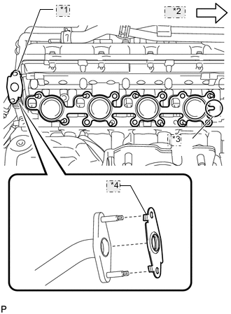
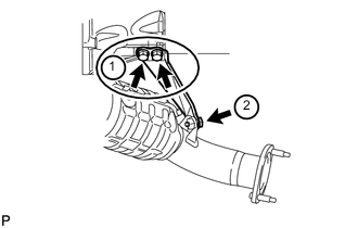
*1 No. 2 Air Tube *2 Front *3 Tab *4 Claw w/ Secondary Air Injection System:
-
Install a new gasket to the cylinder head and a new gasket to the No. 2 air tube.
Tech Tips
-
Install the exhaust manifold gasket with the gasket tab facing toward the front of the engine.
-
Install the air tube gasket with the gasket claws facing the tube side.
-
-
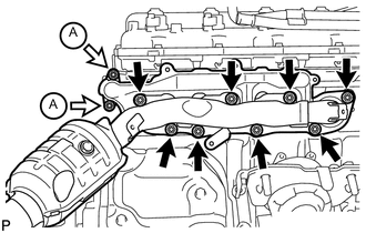
Temporarily install the exhaust manifold with the 2 nuts labeled A and 8 new nuts.
-
Uniformly tighten the nuts that are not labeled A, and then tighten the 2 nuts labeled A.
- Torque:
- for nut A
- 10 N*m { 102 kgf*cm, 7 ft.*lbf }
- except nut A
- 30 N*m { 306 kgf*cm, 22 ft.*lbf }
-
-
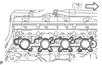
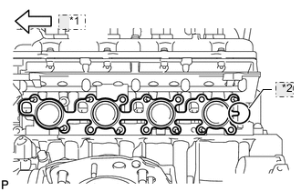
*1 Front *2 Tab w/o Secondary Air Injection System:
-
Install a new gasket to the cylinder head.
Tech Tips
Install the exhaust manifold gasket with the gasket tab facing toward the front of the engine.
-
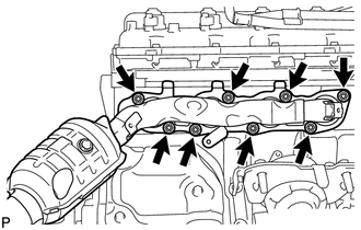
Temporarily install the exhaust manifold with the 8 new nuts.
-
Uniformly tighten the 8 nuts.
- Torque:
- 30 N*m { 306 kgf*cm, 22 ft.*lbf }
-
-
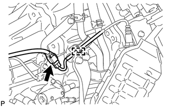
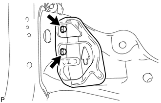
Attach the wire harness clamp to the bracket and connect the connector.
-
-
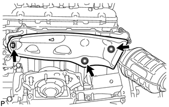
INSTALL NO. 1 EXHAUST MANIFOLD HEAT INSULATOR
-
Install the heat insulator with the 3 bolts.
- Torque:
- 10 N*m { 102 kgf*cm, 7 ft.*lbf }
-
-
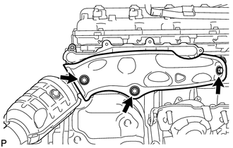
INSTALL NO. 1 MANIFOLD STAY
-
Temporarily install the manifold stay with the 3 bolts.
-
Tighten the 3 bolts in the order shown in the illustration.
- Torque:
- 40 N*m { 408 kgf*cm, 30 ft.*lbf }
-
-
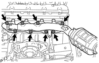
INSTALL EXHAUST MANIFOLD SUB-ASSEMBLY LH
-
*1 Front *2 No. 3 Air Tube *3 Tab *4 Claw w/ Secondary Air Injection System:
-
Install a new gasket to the cylinder head and a new gasket to the No. 3 air tube.
Tech Tips
-
Install the exhaust manifold gasket with the gasket tab facing toward the rear of the engine.
-
Install the air tube gasket with the gasket claws facing the tube side.
-
-
Temporarily install the exhaust manifold with the 2 nuts labeled A and 8 new nuts.
-
Uniformly tighten the nuts that are not labeled A, and then tighten the 2 nuts labeled A.
- Torque:
- for nut A
- 10 N*m { 102 kgf*cm, 7 ft.*lbf }
- except nut A
- 30 N*m { 306 kgf*cm, 22 ft.*lbf }
-
-
*1 Front *2 Tab w/o Secondary Air Injection System:
-
Install a new gasket to the cylinder head.
Tech Tips
Install the exhaust manifold gasket with the gasket tab facing toward the front of the engine.
-
Temporarily install the exhaust manifold with the 8 new nuts.
-
Uniformly tighten the 8 nuts.
- Torque:
- 30 N*m { 306 kgf*cm, 22 ft.*lbf }
-
-
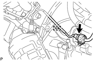
Attach the wire harness clamp to the bracket and connect the connector.
-
-
INSTALL NO. 2 EXHAUST MANIFOLD HEAT INSULATOR
-
Install the heat insulator with the 3 bolts.
- Torque:
- 10 N*m { 102 kgf*cm, 7 ft.*lbf }
-
-
INSTALL NO. 2 MANIFOLD STAY
-
Temporarily install the manifold stay with the 3 bolts.
-
Tighten the 3 bolts in the order shown in the illustration.
- Torque:
- 40 N*m { 408 kgf*cm, 30 ft.*lbf }
-
-
INSTALL PROPELLER SHAFT HEAT INSULATOR
-
Install the heat insulator with the 2 bolts.
- Torque:
- 16 N*m { 160 kgf*cm, 12 ft.*lbf }
-
-
INSTALL FRONT EXHAUST PIPE ASSEMBLY
-
INSTALL FRONT NO. 2 EXHAUST PIPE ASSEMBLY
-
INSTALL CENTER EXHAUST PIPE ASSEMBLY
-
INSTALL TAILPIPE ASSEMBLY
-
INSTALL ENGINE OIL LEVEL DIPSTICK GUIDE
-
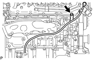
Apply a light coat of engine oil to a new O-ring.
-
Install the O-ring to the guide.
-
Install the dipstick guide with the bolt.
- Torque:
- 10 N*m { 102 kgf*cm, 7 ft.*lbf }
-
Install the dipstick.
-
-
INSPECT FOR EXHAUST GAS LEAK
-
INSTALL FRONT FENDER APRON TRIM PACKING B
-
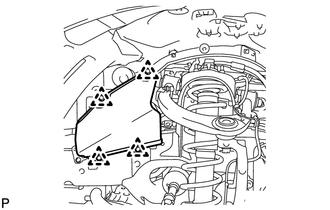
Install the fender apron seal with the 4 clips.
-
-
INSTALL FRONT FENDER APRON TRIM PACKING D
-
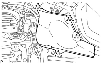
Install the fender apron seal with the 4 clips.
-
-
INSTALL FRONT FENDER APRON TRIM PACKING A
-
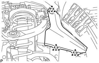
Install the fender apron seal with the 3 clips.
-
-
INSTALL FRONT FENDER APRON TRIM PACKING C
-
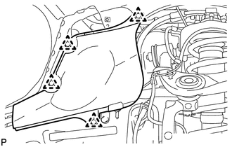
Install the fender apron seal with the 4 clips.
-
-
INSTALL NO. 2 ENGINE UNDER COVER
-
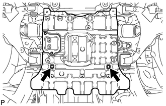
Install the No. 2 engine under cover with the 2 bolts.
- Torque:
- 29 N*m { 296 kgf*cm, 21 ft.*lbf }
-
-
INSTALL NO. 1 ENGINE UNDER COVER SUB-ASSEMBLY
-
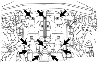
Install the No. 1 engine under cover with the 10 bolts.
- Torque:
- 29 N*m { 296 kgf*cm, 21 ft.*lbf }
-
-
INSTALL FRONT FENDER SPLASH SHIELD SUB-ASSEMBLY LH
-
INSTALL FRONT FENDER SPLASH SHIELD SUB-ASSEMBLY RH
-
INSTALL UPPER RADIATOR SUPPORT SEAL