FUEL SENDER GAUGE ASSEMBLY(for Fuel Sub Tank) INSTALLATION
PROCEDURE
-
INSTALL FUEL SENDER GAUGE ASSEMBLY
-
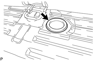
Install a new gasket to the fuel sender gauge assembly.
-
Install the sender gauge with the 5 screws.
- Torque:
- 1.5 N*m { 15 kgf*cm, 13 in.*lbf }
Note
Be careful not to bend the arm of the fuel sender gauge assembly.
-
Connect the fuel sender gauge connector.
-
-
INSTALL REAR FLOOR SERVICE HOLE COVER
-
Install the rear floor service hole cover with new butyl tape.
-
-
INSTALL REAR NO. 7 AIR DUCT
-
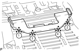
Attach the 4 clips to install the rear No. 7 air duct.
Tech Tips
Attach the clips in the order shown in the illustration.
-
-
INSTALL REAR FLOOR MAT ASSEMBLY
-
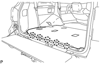
Attach the 5 clips to install the rear floor mat assembly.
-
-
INSTALL REAR AIR DUCT GUIDE
-
INSTALL AIR DUCT PLUG
-
INSTALL FRONT QUARTER TRIM PANEL ASSEMBLY LH
-
INSTALL FRONT QUARTER TRIM PANEL ASSEMBLY RH
-
CONNECT CABLE TO NEGATIVE BATTERY TERMINAL
Note
When disconnecting the cable, some systems need to be initialized after the cable is reconnected Click here.
-
Connect the cables to the negative (-) main battery and sub-battery terminals.
-
-
CHECK SRS WARNING LIGHT