FUEL INJECTOR INSPECTION

PROCEDURE
-
INSPECT FUEL INJECTOR ASSEMBLY
-
Measure the resistance according to the value(s) in the table below.
Standard Resistance Tester Connection Condition Specified Condition 1 - 2 20°C (68°F) 11.6 to 12.4 Ω If the result is not as specified, replace the injector assembly.
-
Inspect the injection volume.
CAUTION:
This test involves high-pressure fuel and electricity. Take all precautions regarding safe handling of both the fuel and the electricity. Perform this test in a safe area, and avoid any sparks or flames. Do not smoke.
-
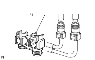
Text in Illustration *1 Fuel Pipe Clamp Remove the fuel pipe clamp.
-
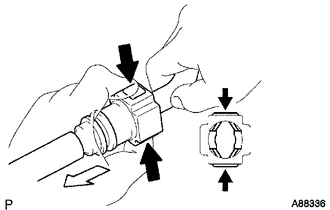
Disconnect the fuel tube.
Text in Illustration 
Pinch 
Pull -
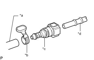
Text in Illustration *a SST (Hose) *b SST (Hose Band) *c SST (Fuel Tube Connector) *d Fuel Pipe Connect SST to the fuel pipe.
- SST
- 09268-31014 ( 09268-41500, 09268-41700, 95336-08070 )
-
Install the O-ring to the fuel injector.
-
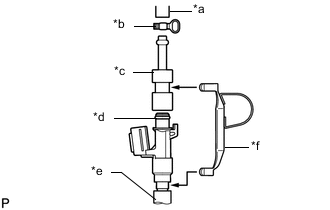
Install SST and the tube to the fuel injector.
- SST
- 09268-31014 ( 09268-41300, 09268-41600, 09268-41700, 95336-08070 )
Text in Illustration *a SST (Hose) *b SST (Hose Band) *c SST (Adapter) *d O-ring *e Vinyl Tube *f SST (Clamp) -
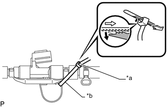
Text in Illustration *a Lock *b SST (Tie Band) Pass SST (tie band) through the loop on the handle of SST (clamp) to secure SST (clamp) to SST (adapter).
- SST
- 09268-31014 ( 09268-41800 )
Note
-
As SST (tie band) does not completely prevent SST (clamp) from becoming loose, do not subject the parts to any impacts while using them.
-
Before using SST (tie band), make sure that there is no deterioration, damage or cracks. If there are any abnormalities, replace SST.
Tech Tips
When removing SST (tie band), disengage the lock.
-
Check that SST (clamp) and SST (adapter) cannot be easily separated.
-
Install a vinyl tube to the injector.
-
Put the injector into a graduated cylinder.
CAUTION:
Install a strong rubber tube onto the injector to prevent gasoline from splashing.
-
Operate the fuel pump (turn the engine switch on (IG)).
-
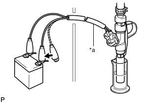
Connect SST (wire) to the injector and the battery for 15 seconds, and measure the injection volume with the graduated cylinder. Test each injector 2 or 3 times.
- SST
- 09842-30090
Standard injection volume 83 to 99 cm3 (5.0 to 6.0 cu in.) per 15 seconds Difference between each injector 16 cm3 (1.0 cu in.) or less Text in Illustration *a SST (Wire) Connect If the injection volume is not as specified, replace the injector assembly.
-
-
Check for fuel drop.
-
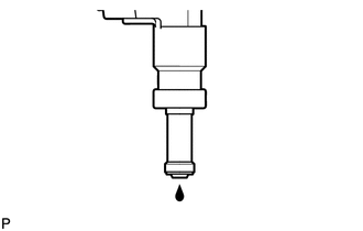
In the condition above, disconnect the tester probes of SST (wire) from the battery and check for fuel drop from the injector.
Standard fuel drop 1 drop or less in 12 minutes If the fuel drop is not as specified, replace the injector assembly.
-
-