CYLINDER HEAD REPLACEMENT

PROCEDURE
-
REPLACE VALVE GUIDE BUSH
-
Gradually heat the cylinder head to 80 to 100°C (176 to 212°F).
-
Place the cylinder head on a wooden block.
-
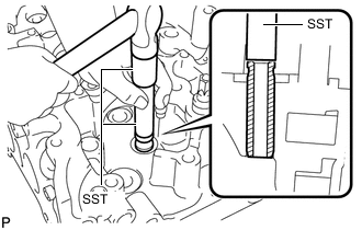
Using SST, tap out the valve guide bush.
- SST
- 09201-10000 ( 09201-01060 )
- 09950-70010 ( 09951-07100 )
-
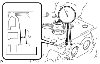
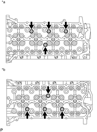
Text in Illustration *a Valve Guide Bush Bore Diameter Using a caliper gauge, measure the bush bore diameter of the cylinder head.
Standard valve guide bush bore diameter 10.985 to 11.006 mm (0.432 to 0.433 in.) If the valve guide bush bore diameter of the cylinder head is more than 11.006 mm (0.433 in.), machine the valve guide bush bore to the dimension of 11.035 to 11.056 mm (0.434 to 0.435 in.).
Standard Valve Guide Bush Diameter Item Specified Condition STD 11.033 to 11.044 mm (0.434 to 0.435 in.) O/S 0.05 11.083 to 11.094 mm (0.436 to 0.437 in.) If the valve guide bush bore diameter of the cylinder head is more than 11.056 mm (0.435 in.), replace the cylinder head .
-
Gradually heat the cylinder head to 80 to 100°C (176 to 212°F).
-
Place the cylinder head on a wooden block.
-
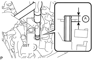
Using SST, tap in a new valve guide bush to the specified protrusion height A shown in the illustration.
- SST
- 09201-10000 ( 09201-01060 )
- 09950-70010 ( 09951-07100 )
Standard protrusion height 9.0 to 9.4 mm (0.354 to 0.370 in.) -
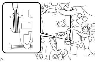
Using a sharp 6.0 mm reamer, ream the valve guide bush to obtain the standard specified clearance between the valve guide bush and valve stem.
Standard Overall Length Item Specified Condition Intake 0.025 to 0.060 mm (0.000984 to 0.00236 in.) Exhaust 0.035 to 0.070 mm (0.00138 to 0.00276 in.)
-
-
REPLACE HEAD STRAIGHT SCREW PLUG
-
Text in Illustration *a RH *b LH Using a 6 mm hexagon wrench, remove the head straight screw plug and gasket.
-
Using a 6 mm hexagon wrench, install a new gasket and head straight screw plug.
- Torque:
- 25 N*m { 255 kgf*cm, 18 ft.*lbf }
-
-
REPLACE RING PIN
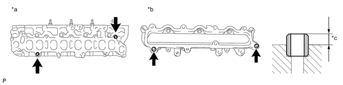
Text in Illustration *a Cylinder Head Side *b Intake Manifold Side *c Protrusion Tech Tips
It is not necessary to remove the ring pin unless it is being replaced.
-
Remove the ring pins.
-
Using a plastic-faced hammer, tap in new ring pins.
Standard protrusion 4.4 to 5.6 mm (0.173 to 0.220 in.)
-
-
REPLACE STUD BOLT
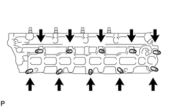
Tech Tips
If a stud bolt is deformed or the threads are damaged, replace it.
-
Using an E8 "TORX" wrench, remove the stud bolts.
-
Using an E8 "TORX" wrench, install new stud bolts.
- Torque:
- 12 N*m { 122 kgf*cm, 9 ft.*lbf }
-