ENGINE UNIT INSTALLATION

PROCEDURE
-
INSTALL FUEL INJECTOR SEAL (w/ DPF)
-
INSTALL EXHAUST FUEL ADDITION INJECTOR ASSEMBLY (w/ DPF)
-
INSTALL COMPRESSOR BRACKET
-
Install the compressor bracket with the bolt.
- Torque:
- 21 N*m { 214 kgf*cm, 15 ft.*lbf }
-
-
INSTALL V-RIBBED BELT TENSIONER ASSEMBLY
-
INSTALL STIFFENER INSULATOR RH
-
INSTALL OIL PRESSURE REGULATOR ASSEMBLY
-
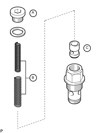
Hold the oil pressure regulator body in a vise between aluminum plates.
-
Apply a light coat of engine oil to the oil pump relief valve labeled C.
-
Install the oil pump relief valve labeled C to the oil pressure regulator body.
-
Install the 2 springs labeled B to the oil pressure regulator body.
-
Using a 10 mm hexagon wrench, install a new gasket and the oil pump relief valve plug labeled A.
- Torque:
- 50 N*m { 510 kgf*cm, 37 ft.*lbf }
-
Apply a light coat of engine oil to a new O-ring, and install it to the oil pressure regulator body.
-
Using a 26 mm wrench, install a new gasket and the oil pressure regulator assembly.
- Torque:
- 86 N*m { 877 kgf*cm, 63 ft.*lbf }
-
-
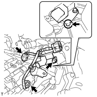
INSTALL OIL FILTER BRACKET DRAIN COCK ASSEMBLY
-
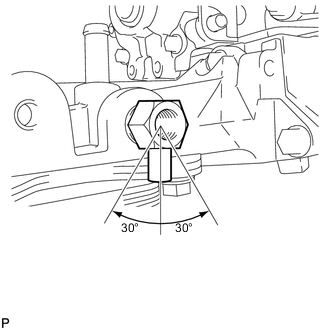
Install the oil filter bracket drain cock assembly.
- Torque:
- 20 N*m { 204 kgf*cm, 15 ft.*lbf }
-
Using a 17 mm wrench, rotate the oil filter bracket drain cock assembly clockwise (360°) and align the position of the drain hole so that it is within the range shown in the illustration after tightening the oil filter bracket drain cock assembly to the specified torque.
Note
-
As the oil filter bracket sub-assembly may be damaged, the maximum tightening torque should be 80 N*m (816 kgf*cm, 59 ft.*lbf) or less.
-
Do not rotate the oil filter bracket drain cock assembly more than 1 revolution (360°) after tightening the oil filter bracket drain cock assembly with the specified torque.
-
Do not expose the oil filter bracket drain cock assembly to coolant within 1 hour after installation.
-
-
Install the oil filter drain cock plug.
- Torque:
- 13 N*m { 130 kgf*cm, 9 ft.*lbf }
-
-
INSTALL OIL TANK BRACKET
-
Install the oil tank bracket with the bolt.
- Torque:
- 10 N*m { 102 kgf*cm, 7 ft.*lbf }
-
-
INSTALL NO. 2 CYLINDER BLOCK INSULATOR
-
INSTALL ENGINE MOUNTING BRACKET LH
-
Install the engine mounting bracket LH with the 4 bolts.
- Torque:
- 80 N*m { 816 kgf*cm, 59 ft.*lbf }
-
-
INSTALL NO. 2 WATER BY-PASS PIPE SUB-ASSEMBLY
-
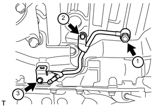
Temporarily install a new gasket and No. 2 water by-pass pipe sub-assembly with the union bolt and 2 bolts.
-
Tighten the union bolt and 2 bolts of the No. 2 water by-pass pipe sub-assembly in the order shown in the illustration.
- Torque:
- for union bolt
- 35 N*m { 357 kgf*cm, 26 ft.*lbf }
- for bolt
- 10 N*m { 102 kgf*cm, 7 ft.*lbf }
-
-
INSTALL NO. 3 VACUUM TRANSMITTING PIPE SUB-ASSEMBLY
-
Install the No. 3 vacuum transmitting pipe sub-assembly with the 2 bolts.
- Torque:
- 6.0 N*m { 61 kgf*cm, 53 in.*lbf }
-
Connect the vacuum hose.
-
-
INSTALL TURBOCHARGER WIRE
-
Install the turbocharger wire with the 2 bolts.
- Torque:
- 21 N*m { 214 kgf*cm, 15 ft.*lbf }
-
Attach the 3 wire harness clamps.
-
-
INSTALL NO. 2 INTAKE AIR CONNECTOR BRACKET
-
Install the No. 2 intake air connector bracket with the bolt.
- Torque:
- 21 N*m { 214 kgf*cm, 15 ft.*lbf }
-
Attach the 2 wire harness clamps.
-
-
INSTALL NO. 1 CYLINDER BLOCK INSULATOR
-
INSTALL ENGINE MOUNTING BRACKET RH
-
Install the engine mounting bracket RH with the 4 bolts.
- Torque:
- 80 N*m { 816 kgf*cm, 59 ft.*lbf }
-
-
INSTALL NO. 4 VACUUM TRANSMITTING PIPE SUB-ASSEMBLY
-
Install the No. 4 vacuum transmitting pipe sub-assembly with the 2 bolts.
- Torque:
- 6.0 N*m { 61 kgf*cm, 53 in.*lbf }
-
Connect the vacuum hose.
-
-
INSTALL NO. 1 WATER BY-PASS PIPE SUB-ASSEMBLY
-
Temporarily install a new gasket and the No. 1 water by-pass pipe sub-assembly with the union bolt and bolt.
-
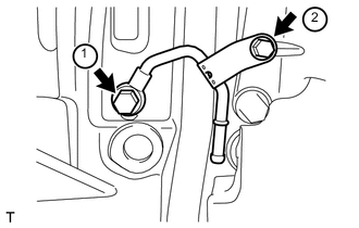
Tighten the union bolt and bolt of the No. 1 water by-pass pipe sub-assembly in the order shown in the illustration.
- Torque:
- for union bolt
- 35 N*m { 357 kgf*cm, 26 ft.*lbf }
- for bolt
- 10 N*m { 102 kgf*cm, 7 ft.*lbf }
-
-
INSTALL AIR TUBE SUPPORT
-
Install the air tube support with the 2 bolts.
- Torque:
- 21 N*m { 214 kgf*cm, 15 ft.*lbf }
-
-
INSTALL NO. 1 INTAKE AIR CONNECTOR BRACKET
-
Install the No. 1 intake air connector bracket with the 2 bolts.
- Torque:
- 21 N*m { 214 kgf*cm, 15 ft.*lbf }
-
-
INSTALL REAR CYLINDER HEAD PLATE LH (w/o EGR System)
-
Install a new gasket and the rear cylinder head plate LH with the 2 bolts.
- Torque:
- 29 N*m { 296 kgf*cm, 21 ft.*lbf }
Tech Tips
The gasket claw should face toward the rear cylinder head plate LH.
-
-
INSTALL REAR CYLINDER HEAD PLATE RH (w/o EGR System)
-
Install a new gasket and the rear cylinder head plate RH with the 2 bolts.
- Torque:
- 29 N*m { 296 kgf*cm, 21 ft.*lbf }
Tech Tips
The gasket claw should face toward the rear cylinder head plate RH.
-
-
INSTALL CYLINDER HEAD COVER SILENCER LH (w/o DPF)
-
Install the cylinder head cover silencer LH with the 3 bolts.
- Torque:
- 5.0 N*m { 51 kgf*cm, 44 in.*lbf }
-
-
INSTALL CYLINDER HEAD COVER SILENCER RH (w/o DPF)
-
Install the cylinder head cover silencer RH with the 3 bolts.
- Torque:
- 5.0 N*m { 51 kgf*cm, 44 in.*lbf }
-
-
INSTALL NO. 1 VACUUM TRANSMITTING PIPE SUB-ASSEMBLY (w/o DPF)
-
INSTALL NO. 1 VACUUM SWITCHING VALVE ASSEMBLY (w/o DPF)
-
INSTALL FAN BRACKET SUB-ASSEMBLY
-
INSTALL NO. 2 IDLER PULLEY BRACKET (w/ Viscous Heater)
-
INSTALL NO. 2 IDLER PULLEY (w/ Viscous Heater)
-
INSTALL NO. 3 ENGINE HANGER
-
Install the No. 3 engine hanger with the 2 bolts.
- Torque:
- 43 N*m { 438 kgf*cm, 32 ft.*lbf }
-
-
INSTALL NO. 1 INTERCOOLER SUPPORT BRACKET
-
Install the No. 1 intercooler support bracket with the 2 bolts.
- Torque:
- 21 N*m { 214 kgf*cm, 15 ft.*lbf }
-
-
INSTALL FUEL PUMP MOTOR WIRE
-
Install the fuel pump motor wire with the bolt.
- Torque:
- 6.0 N*m { 61 kgf*cm, 53 in.*lbf }
Tech Tips
Attach the claw of the bracket to the timing gear case sub-assembly when installing the bracket.
-
-
INSTALL GLOW PLUG ASSEMBLY
-
INSTALL NO. 1 GLOW PLUG CONNECTOR
-
INSTALL NO. 1 AND NO. 2 WATER OUTLET PIPES AND WATER BY-PASS OUTLET
-
Align the painted mark of the No. 1 water hose joint with the protrusion of the water by-pass outlet and connect the water by-pass outlet to the No. 1 water hose joint.
-
Align the painted mark of the No. 1 water hose joint with the painted mark of the No. 2 water outlet pipe and connect the No. 2 water outlet pipe to the No. 1 water hose joint.
-
Connect a new gasket and the No. 1 water outlet pipe and No. 2 water outlet pipe with the 2 bolts.
- Torque:
- 21 N*m { 214 kgf*cm, 15 ft.*lbf }
Tech Tips
The gasket claws can face the No. 1 water outlet pipe or No. 2 water outlet pipe.
-
-
INSTALL WATER OUTLET PIPE
-
Install 2 new gaskets and the water outlet pipe with the 4 bolts.
- Torque:
- 21 N*m { 214 kgf*cm, 15 ft.*lbf }
Tech Tips
The gasket claw should face toward the water outlet pipe.
-
-
INSTALL WATER OUTLET
-
Install a new gasket and the water outlet with the 2 bolts, and then connect the water outlet to the No. 2 water hose joint.
- Torque:
- 21 N*m { 214 kgf*cm, 15 ft.*lbf }
-
-
INSTALL NO. 2 INTERCOOLER SUPPORT BRACKET
-
Install the No. 2 intercooler support bracket with the 2 bolts.
- Torque:
- 43 N*m { 438 kgf*cm, 32 ft.*lbf }
-
-
INSTALL ENGINE COOLANT TEMPERATURE SENSOR
-
CONNECT INLET WATER HOSE
-
INSTALL STARTER HOSE BRACKET
-
INSTALL STARTER ASSEMBLY
-
INSTALL TIMING GEAR COVER INSULATOR
-
w/o Viscous Heater:
Install the timing gear cover insulator with the 2 bolts.
- Torque:
- 21 N*m { 214 kgf*cm, 15 ft.*lbf }
-
w/ Viscous Heater:
Install the timing gear cover insulator.
-
-
INSTALL THERMOSTAT
-
INSTALL WATER INLET
-
INSTALL NO. 1 IDLER PULLEY BRACKET (w/ Viscous Heater)
-
INSTALL VISCOUS WITH MAGNET CLUTCH HEATER ASSEMBLY (w/ Viscous Heater)
-
INSTALL NO. 2 TURBOCHARGER SUB-ASSEMBLY WITH NO. 2 EXHAUST MANIFOLD
-
INSTALL NO. 2 VENTILATION TUBE SUB-ASSEMBLY
-
INSTALL NO. 2 TURBOCHARGER STAY
-
CONNECT NO. 2 OUTLET TURBO OIL HOSE
-
INSTALL NO. 2 TURBO WATER PIPE SUB-ASSEMBLY
-
INSTALL FRONT WATER BY-PASS JOINT
-
INSTALL NO. 3 TURBO WATER PIPE SUB-ASSEMBLY
-
INSTALL NO. 2 EXHAUST MANIFOLD HEAT INSULATOR
-
INSTALL NO. 2 TURBO WATER HOSE
-
INSTALL BREATHER PLUG LH
-
INSTALL NO. 3 VENTILATION HOSE
-
INSTALL TURBOCHARGER SUB-ASSEMBLY WITH EXHAUST MANIFOLD
-
INSTALL VENTILATION TUBE SUB-ASSEMBLY
-
INSTALL TURBOCHARGER STAY
-
INSTALL NO. 1 TURBO WATER PIPE SUB-ASSEMBLY
-
CONNECT TURBO OIL OUTLET HOSE
-
INSTALL NO. 1 EXHAUST MANIFOLD HEAT INSULATOR
-
INSTALL NO. 2 TURBO WATER HOSE
-
INSTALL BREATHER PLUG RH
-
INSTALL NO. 2 VENTILATION HOSE
-
INSTALL GENERATOR ASSEMBLY
-
INSTALL INTAKE AIR CONNECTOR PIPE
-
INSTALL ENGINE OIL LEVEL DIPSTICK GUIDE
-
INSTALL VACUUM PUMP ASSEMBLY