FUEL TANK INSTALLATION
PROCEDURE
-
INSTALL NO. 1 FUEL TANK HEAT INSULATOR
-
Install the No. 1 fuel tank heat insulator with the 4 clips.
-
Install the fuel tube clamp to the No. 1 fuel tank heat insulator.
-
-
INSTALL FUEL TANK TO FILLER PIPE HOSE
-
Text in Illustration *a Fuel Tank Side Mark *b Hose Side Mark Install the fuel tank to filler pipe hose to the fuel tank sub-assembly as shown in the illustration and tighten the hose clamp.
-
-
INSTALL FUEL SUCTION WITH PUMP AND GAUGE TUBE ASSEMBLY
-
INSTALL FUEL TANK MAIN TUBE, FUEL TANK RETURN TUBE AND NO. 2 FUEL TANK MAIN TUBE SUB-ASSEMBLY (for Double Tank Type)
-
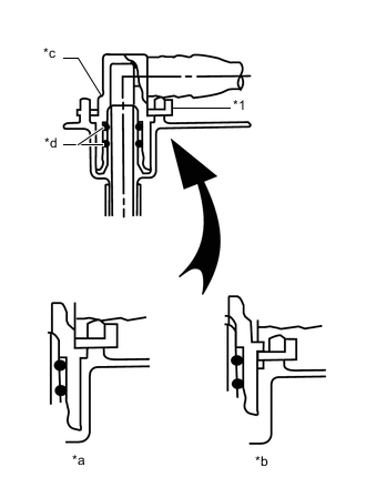
Text in Illustration *1 Tube Joint Clip *a CORRECT *b INCORRECT *c Fuel Tube Joint *d O-Ring Install the 3 fuel tube joints with the 3 tube joint clips.
Note
-
Check that there are no scratches or foreign objects on the connecting parts.
-
Check that the fuel tube joints are inserted securely.
-
Check that the tube joint clips are on the collars of the fuel tube joints.
-
After installing the tube joint clips, check that the fuel tube joints cannot be pulled off.
-
-
for G.C.C. Countries:
-
Attach the 2 clamps and install the No. 2 fuel tank main tube sub-assembly.
-
Attach the clamp and install the fuel tank return tube sub-assembly.
-
Attach the clamp and install the fuel tank main tube sub-assembly.
-
-
except G.C.C. Countries:
-
Attach the 2 clamps and install the No. 2 fuel tank main tube sub-assembly.
-
Attach the clamp and install the fuel tank return tube sub-assembly.
-
Attach the clamp and install the fuel tank main tube sub-assembly.
-
-
-
CONNECT FUEL HOSE (for Double Tank Type)
-
for G.C.C. Countries:
Install the fuel hose to the fuel suction tube sub-assembly, and slide the clip to secure the hose.
-
-
INSTALL FUEL TANK MAIN TUBE SUB-ASSEMBLY AND FUEL TANK RETURN TUBE SUB-ASSEMBLY (for Single Tank Type)
-
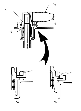
Text in Illustration *1 Tube Joint Clip *a CORRECT *b INCORRECT *c Fuel Tube Joint *d O-Ring *e Fuel Tube Install the 2 fuel tank tubes with the 2 tube joint clips.
Note
-
Check that there are no scratches or foreign objects on the connecting parts.
-
Check that the fuel tube joints are inserted securely.
-
Check that the tube joint clips are on the collars of the fuel tube joints.
-
After installing the tube joint clips, check that the fuel tube joints cannot be pulled off.
-
-
Attach the clamp and install the fuel tank return tube sub-assembly.
-
Attach the clamp and install the fuel tank main tube sub-assembly.
-
-
INSTALL FUEL TANK SUB-ASSEMBLY
-
Set the fuel tank sub-assembly on an engine lifter and raise the fuel tank sub-assembly.
Note
Do not allow the fuel tank sub-assembly to contact the vehicle, especially the differential.
-
Raise the engine lifter.
-
Install the 2 fuel tank band sub-assemblies with the 2 pins and 2 clips.
-
Connect the 2 fuel tank band sub-assemblies with the 2 bolts.
- Torque:
- 40 N*m { 408 kgf*cm, 30 ft.*lbf }
-
-
CONNECT FUEL TANK TO FILLER PIPE HOSE (for Double Tank Type)
-
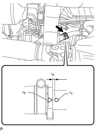
Text in Illustration *a 0 to 0.3 mm (0 to 0.0118 in.) *b Fuel Tank to Filler Pipe Hose Side Mark *c Fuel Tank Inlet Pipe Side Mark Connect the fuel tank to filler pipe hose to the fuel tank to filler pipe sub-assembly as shown in the illustration and tighten the hose clamp.
-
-
CONNECT FUEL TANK TO FILLER PIPE HOSE (for Single Tank Type)
-
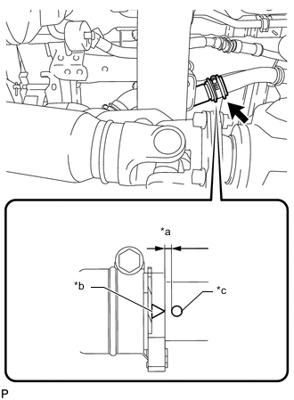
Text in Illustration *a 0 to 0.3 mm (0 to 0.0118 in.) *b Fuel Tank to Filler Pipe Hose Side Mark *c Fuel Tank Inlet Pipe Side Mark Connect the fuel tank to filler pipe hose to the fuel tank to filler pipe sub-assembly as shown in the illustration and tighten the hose clamp.
-
-
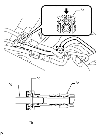
CONNECT FUEL TANK BREATHER TUBE (for Double Tank Type)
-
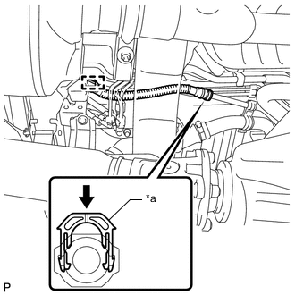
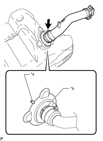
Text in Illustration *a Retainer 
Push Connect the fuel tank breather tube to the fuel tank to filler pipe sub-assembly and push the retainer.
Note
-
Before installing the tube connectors to the pipes, check if there is any damage or foreign matter in the connectors.
-
After the connection, check if the connectors and pipes are securely connected by trying to pull them apart.
Tech Tips
Push the parts together firmly until a "click" sound is heard.
-
-
Attach the fuel tube clamp.
-
-
CONNECT FUEL TANK BREATHER TUBE (for Single Tank Type)
-
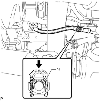
Text in Illustration *a Retainer Push Connect the fuel tank breather tube to the fuel tank to filler pipe sub-assembly and push the retainer.
Note
-
Before installing the tube connectors to the pipes, check if there is any damage or foreign matter in the connectors.
-
After the connection, check if the connectors and pipes are securely connected by trying to pull them apart.
Tech Tips
Push the parts together firmly until a "click" sound is heard.
-
-
Attach the fuel tube clamp.
-
-
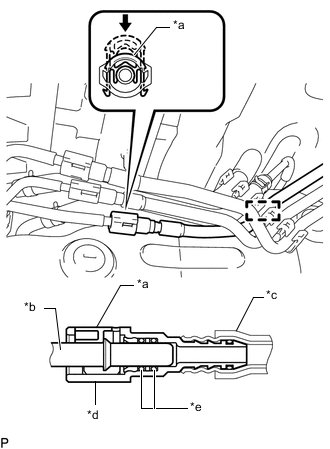
CONNECT NO. 2 FUEL TANK BREATHER TUBE (for Double Tank Type)
-
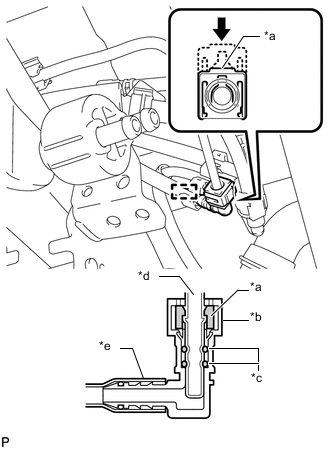
Text in Illustration *a Retainer *b Connector *c O-Ring *d Pipe *e Nylon Tube Push except G.C.C. Countries:
-
Connect the No. 2 fuel tank breather tube and push the retainer.
Note
-
Before installing the tube connectors to the pipes, check if there is any damage or foreign matter in the connectors.
-
After the connection, check if the connectors and pipes are securely connected by trying to pull them apart.
Tech Tips
Push the parts together firmly until a "click" sound is heard.
-
-
Attach the fuel tube clamp.
-
-
-
CONNECT NO. 2 FUEL MAIN TUBE SUB-ASSEMBLY (for Double Tank Type)
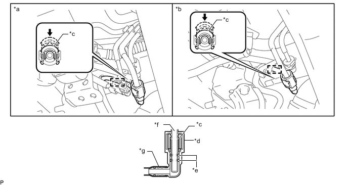
Text in Illustration *a except G.C.C. Countries *b for G.C.C. Countries *c Retainer *d Connector *e O-Ring *f Pipe *g Nylon Tube - - Push - -
-
Connect the No. 2 fuel tank main tube sub-assembly and push the retainer.
Note
-
Before installing the tube connectors to the pipes, check if there is any damage or foreign matter in the connectors.
-
After the connection, check if the connectors and pipes are securely connected by trying to pull them apart.
Tech Tips
Push the parts together firmly until a "click" sound is heard.
-
-
Attach the fuel tube clamp.
-
-
CONNECT FUEL HOSE (for Double Tank Type)
-
for G.C.C. Countries:
-
Connect the fuel hose to the pipe, and slide the clip to secure the hose.
-
Attach the fuel tube clamp.
-
-
-
CONNECT NO. 1 FUEL EMISSION TUBE SUB-ASSEMBLY (for Double Tank Type)
-
Text in Illustration *a Retainer *b Connector *c O-Ring *d Pipe *e Nylon Tube Push except G.C.C. Countries:
-
Connect the No. 1 fuel emission tube sub-assembly and push the retainer.
Note
-
Before installing the tube connectors to the pipes, check if there is any damage or foreign matter in the connectors.
-
After the connection, check if the connectors and pipes are securely connected by trying to pull them apart.
Tech Tips
Push the parts together firmly until a "click" sound is heard.
-
-
Attach the fuel tube clamp.
-
-
Text in Illustration *a Retainer *b Pipe *c Nylon Tube *d Connector *e O-Ring Push for G.C.C. Countries:
-
Connect the No. 1 fuel emission tube sub-assembly and push the retainer.
Note
-
Before installing the tube connectors to the pipes, check if there is any damage or foreign matter in the connectors.
-
After the connection, check if the connectors and pipes are securely connected by trying to pull them apart.
Tech Tips
Push the parts together firmly until a "click" sound is heard.
-
-
Attach the fuel tube clamp.
-
-
-
CONNECT FUEL TANK RETURN TUBE (for Double Tank Type)
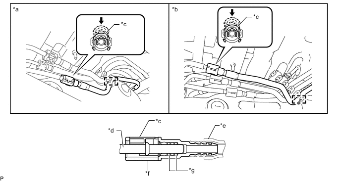
Text in Illustration *a except G.C.C. Countries *b for G.C.C. Countries *c Retainer *d Pipe *e Nylon Tube *f Connector *g O-Ring - - Push - -
-
Connect the fuel tank return tube and push the retainer.
Note
-
Before installing the tube connectors to the pipes, check if there is any damage or foreign matter in the connectors.
-
After the connection, check if the connectors and pipes are securely connected by trying to pull them apart.
Tech Tips
Push the parts together firmly until a "click" sound is heard.
-
-
Attach the fuel tube clamp.
-
-
CONNECT FUEL TANK RETURN TUBE (for Single Tank Type)
-
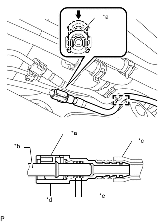
Text in Illustration *a Retainer *b Pipe *c Nylon Tube *d Connector *e O-Ring Push Connect the fuel tank return tube and push the retainer.
Note
-
Before installing the tube connectors to the pipes, check if there is any damage or foreign matter in the connectors.
-
After the connection, check if the connectors and pipes are securely connected by trying to pull them apart.
Tech Tips
Push the parts together firmly until a "click" sound is heard.
-
-
Attach the fuel tube clamp.
-
-
CONNECT NO. 2 FUEL TANK BREATHER HOSE (for Double Tank Type)
-
for G.C.C. Countries:
-
Connect the No. 2 fuel tank breather hose to the pipe, and slide the clip to secure the hose.
-
Attach the fuel pipe clamp.
-
-
-
CONNECT NO. 2 FUEL TANK BREATHER TUBE (for Single Tank Type)
-
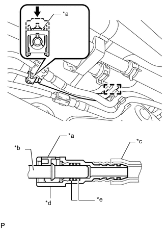
Text in Illustration *a Retainer *b Pipe *c Nylon Tube *d Connector *e O-Ring Push Connect the No. 2 fuel tank breather tube and push the retainer.
Note
-
Before installing the tube connectors to the pipes, check if there is any damage or foreign matter in the connectors.
-
After the connection, check if the connectors and pipes are securely connected by trying to pull them apart.
Tech Tips
Push the parts together firmly until a "click" sound is heard.
-
-
Attach the fuel tube clamp.
-
-
CONNECT FUEL TANK MAIN TUBE SUB-ASSEMBLY (for Double Tank Type)
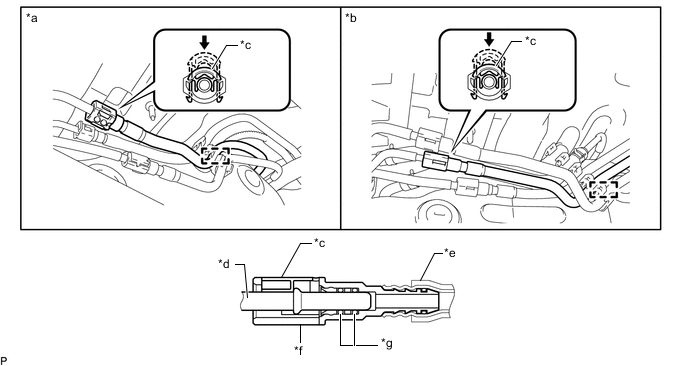
Text in Illustration *a except G.C.C. Countries *b for G.C.C. Countries *c Retainer *d Pipe *e Nylon Tube *f Connector *g O-Ring - - Push - -
-
Connect the fuel tank main tube sub-assembly and push the retainer.
Note
-
Before installing the tube connectors to the pipes, check if there is any damage or foreign matter in the connectors.
-
After the connection, check if the connectors and pipes are securely connected by trying to pull them apart.
Tech Tips
Push the parts together firmly until a "click" sound is heard.
-
-
Attach the fuel tube clamp.
-
-
CONNECT FUEL TANK MAIN TUBE SUB-ASSEMBLY (for Single Tank Type)
-
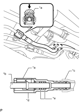
Text in Illustration *a Retainer *b Pipe *c Nylon Tube *d Connector *e O-Ring Push Connect the fuel tank main tube sub-assembly and push the retainer.
Note
-
Before installing the tube connectors to the pipes, check if there is any damage or foreign matter in the connectors.
-
After the connection, check if the connectors and pipes are securely connected by trying to pull them apart.
Tech Tips
Push the parts together firmly until a "click" sound is heard.
-
-
Attach the fuel tube clamp.
-
-
INSTALL NO. 1 FUEL TANK PROTECTOR SUB-ASSEMBLY
-
Install the No. 1 fuel tank protector sub-assembly with the 5 bolts.
- Torque:
- 20 N*m { 204 kgf*cm, 15 ft.*lbf }
-
-
INSTALL FUEL TANK CAP ASSEMBLY
-
INSTALL REAR FLOOR NO. 2 SERVICE HOLE COVER
-
Connect the fuel pump and fuel sender gauge connector.
-
Install the rear floor No. 2 service hole cover with new butyl tape.
-
Install the air duct and 2 screws.
-
-
INSTALL FRONT FLOOR CARPET ASSEMBLY
-
INSTALL REAR SEAT ASSEMBLY
-
Install the rear No. 1 seat assembly and rear No. 2 seat assembly Click here.
-
-
CONNECT CABLE TO NEGATIVE BATTERY TERMINAL
Note
When disconnecting the cable, some systems need to be initialized after the cable is reconnected Click here.
-
ADD FUEL
-
INSPECT FOR FUEL LEAK