CAMSHAFT(w/o DPF) REMOVAL

CAUTION / NOTICE / HINT
CAUTION:
When replacing an injector assembly (including interchanging injector assemblies between cylinders), common rail assembly, cylinder head, or intake manifold, replace the corresponding injection pipes with a new one.
PROCEDURE
-
CHECK INJECTOR COMPENSATION CODE
-
PRECAUTION
Note
After turning the engine switch off, waiting time may be required before disconnecting the cable from the battery terminal. Therefore, make sure to read the disconnecting the cable from the battery terminal notice before proceeding with work Click here.
-
DISCONNECT CABLE FROM NEGATIVE BATTERY TERMINAL
Note
When disconnecting the cable some systems need to be initialized after the cable is reconnected Click here.
-
Disconnect the cables from the negative (-) main battery and sub-battery terminals.
-
-
DRAIN ENGINE OIL
-
REMOVE FRONT WHEEL
-
REMOVE FRONT FENDER SPLASH SHIELD SUB-ASSEMBLY LH
-
REMOVE FRONT FENDER SPLASH SHIELD SUB-ASSEMBLY RH
-
REMOVE NO. 1 ENGINE UNDER COVER SUB-ASSEMBLY
-
DRAIN ENGINE COOLANT
-
REMOVE UPPER RADIATOR SUPPORT SEAL
-
REMOVE NO. 3 ENGINE ROOM WIRE
-
REMOVE NO. 1 ENGINE COVER SUB-ASSEMBLY
-
REMOVE AIR CLEANER CAP SUB-ASSEMBLY
-
REMOVE NO. 1 AIR CLEANER HOSE
-
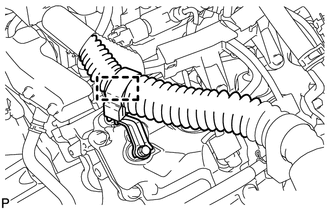
REMOVE INTAKE AIR CONNECTOR
-
REMOVE V-RIBBED BELT (w/ Viscous Heater)
-
REMOVE NO. 1 IDLER PULLEY (w/ Viscous Heater)
-
REMOVE NO. 3 IDLER PULLEY (w/ Viscous Heater)
-
REMOVE V-RIBBED BELT
-
REMOVE FRONT FENDER APRON SEAL FRONT RH
-
REMOVE FRONT FENDER APRON SEAL REAR RH
-
REMOVE FRONT FENDER APRON SEAL FRONT LH
-
REMOVE FRONT FENDER APRON SEAL REAR LH
-
REMOVE VANE PUMP OIL RESERVOIR ASSEMBLY
-
REMOVE NO. 1 OIL RESERVOIR BRACKET
-
REMOVE RADIATOR RESERVOIR ASSEMBLY
-
REMOVE VANE PUMP ASSEMBLY
-
REMOVE OIL COOLER TUBE
-
REMOVE FAN SHROUD WITH FAN
-
REMOVE FRONT FENDER MAIN SEAL LH
-
REMOVE FRONT FENDER MAIN SEAL RH
-
REMOVE FRONT WIPER ARM LH
-
REMOVE FRONT WIPER ARM RH
-
REMOVE HOOD TO COWL TOP SEAL
-
REMOVE COWL TOP VENTILATOR LOUVER SUB-ASSEMBLY
-
REMOVE INTERCOOLER ASSEMBLY
-
REMOVE NO. 1 AIR HOSE
-
REMOVE NO. 2 AIR HOSE
-
REMOVE NO. 2 ENGINE OIL LEVEL DIPSTICK GUIDE
-
REMOVE AIR TUBE SUB-ASSEMBLY RH
-
REMOVE AIR TUBE SUB-ASSEMBLY LH
-
DISCONNECT WATER HOSE SUB-ASSEMBLY
-
REMOVE NO. 3 WATER BY-PASS PIPE (w/o Viscous Heater)
-
REMOVE HEATER WATER PIPE SUB-ASSEMBLY (w/ Viscous Heater)
-
REMOVE NO. 3 AIR TUBE
-
REMOVE AIR CLEANER PIPE
-
REMOVE NO. 4 AIR TUBE
-
REMOVE NO. 2 AIR CLEANER PIPE SUB-ASSEMBLY
-
REMOVE VISCOUS WITH MAGNET CLUTCH HEATER ASSEMBLY (w/ Viscous Heater)
-
REMOVE NO. 1 IDLER PULLEY BRACKET (w/ Viscous Heater)
-
REMOVE NO. 4 WATER BY-PASS PIPE
-
DISCONNECT FUEL HOSE
-
DISCONNECT ENGINE WIRE
-
LH Side:
-
Disconnect the 4 connectors from the injector driver.
-
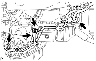
Remove the 2 connectors and detach the wire harness holder from the relay block.
-
Remove the bolt and disconnect the ground wire.
-
Disconnect the wire harness from the wire harness clamp holder.
-
Remove the bolt and disconnect the ground wire from the body panel.
-
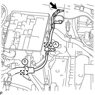
Using a clip remover, detach the ground wire clamp labeled A from the relay block side.
-
Disconnect the wire harness from the wire harness clamp holder labeled B.
-
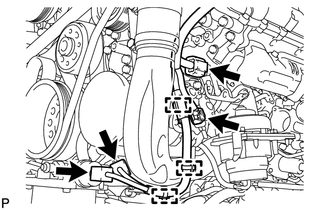
Disconnect the 4 connectors.
-
Using a clip remover, detach the 3 wire harness clamps.
-
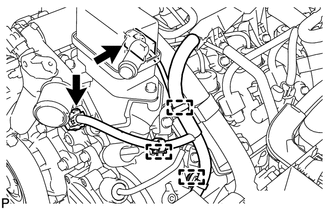
Disconnect the 2 connectors.
-
Using a clip remover, detach the 3 wire harness clamps.
-
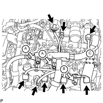
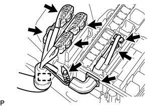
Disconnect the 8 connectors.
-
Remove the 2 bolts labeled A and disconnect the engine wire protector.
-
Remove the bolt labeled B and wire harness bracket.
-
for RHD:
Disconnect the wire harness from the wire harness clamp holder labeled C.
-
-
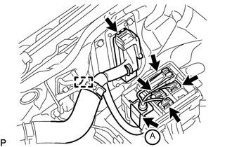
RH Side:
-
Disconnect the 4 connectors.
-
Using a clip remover, detach the 5 wire harness clamps.
-
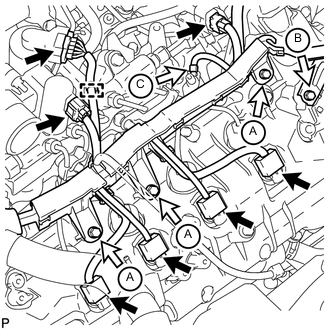
Disconnect the 7 connectors.
-
Using a clip remover, detach the wire harness clamp.
-
Remove the 3 bolts labeled A and disconnect the wire harness protector.
-
Remove the bolt labeled B and wire harness bracket.
-
Remove the nut labeled C and glow plug wire harness.
-
-
for LHD:
-
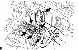
Disconnect the 4 connectors, and detach the wire harness tab labeled A from the relay block.
-
Disconnect the ECM connector.
-
Disconnect the wire harness from the wire harness clamp holder.
-
-
for RHD:
-
Disconnect the wire harness from the wire harness clamp holder.
-
Disconnect the 4 connectors, and detach the wire harness tab labeled A from the relay block.
-
Disconnect the ECM connector.
-
Disconnect the wire harness from the wire harness clamp holder.
-
-
-
REMOVE NO. 2 FUEL PIPE SUB-ASSEMBLY
-
REMOVE NO. 6 INJECTION PIPE SUB-ASSEMBLY
-
REMOVE INJECTION PIPE SUB-ASSEMBLY LH
-
REMOVE COMMON RAIL ASSEMBLY LH
-
REMOVE FUEL FILTER TO INJECTION PUMP FUEL PIPE SUB-ASSEMBLY
-
DISCONNECT NO. 2 ENGINE WIRE
-
REMOVE INJECTION PIPE SUB-ASSEMBLY RH
-
REMOVE NO. 2 IDLER PULLEY (w/ Viscous Heater)
-
REMOVE NO. 2 IDLER PULLEY BRACKET (w/ Viscous Heater)
-
REMOVE NO. 1 VACUUM SWITCHING VALVE ASSEMBLY
-
REMOVE NO. 1 VACUUM TRANSMITTING PIPE SUB-ASSEMBLY
-
REMOVE VACUUM PUMP ASSEMBLY
-
DISCONNECT NO. 2 VENTILATION HOSE
-
DISCONNECT NO. 3 VENTILATION HOSE
-
REMOVE CYLINDER HEAD COVER SILENCER RH
-
REMOVE CYLINDER HEAD COVER SILENCER LH
-
REMOVE NOZZLE HOLDER SEAL RH
-
REMOVE CYLINDER HEAD COVER SUB-ASSEMBLY RH
-
REMOVE NOZZLE HOLDER GASKET RH
-
REMOVE OIL SEPARATOR ASSEMBLY
-
REMOVE NOZZLE HOLDER SEAL LH
-
REMOVE CYLINDER HEAD COVER SUB-ASSEMBLY LH
-
REMOVE NOZZLE HOLDER GASKET LH
-
REMOVE FUEL INJECTOR RH
-
REMOVE FUEL INJECTOR LH
-
REMOVE NO. 1 CAMSHAFT AND NO. 2 CAMSHAFT
-
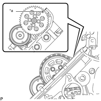
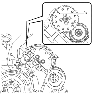
Text in Illustration *a Arrow Rotate the crankshaft clockwise, and align the No. 1 camshaft timing sprocket arrow with the cylinder head upper surface.
-
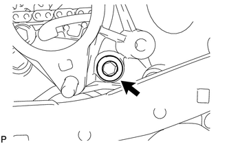
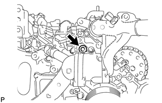
Using a 10 mm hexagon wrench, remove the taper screw plug.
-
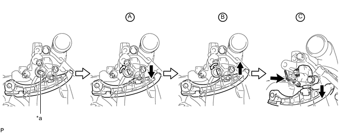
Fix the No. 1 chain tensioner assembly in place.
-
Push the tensioner slipper away from the No. 1 chain tensioner assembly, and move the stopper plate clockwise to release the lock as shown in A.
-
Push down the tensioner slipper and move the stopper plate counterclockwise to set the lock as shown in B.
-
Push the tensioner slipper away from the No. 1 chain tensioner assembly, and insert a hexagon wrench into the stopper plate hole as shown in C.
Note
Do not drop the hexagon wrench into the engine.
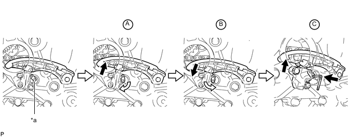
Text in Illustration *a Stopper Plate - -
-
-
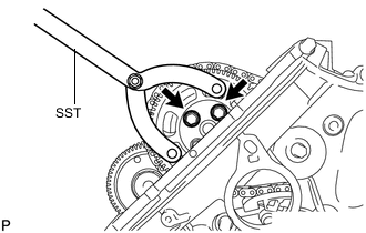
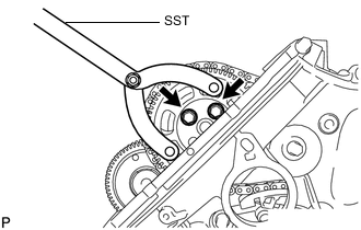
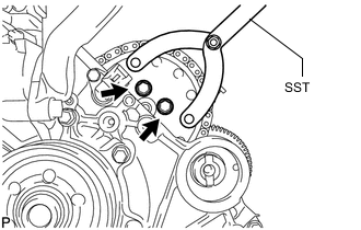
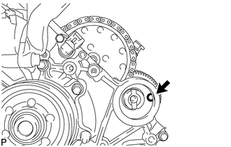
Using SST, hold the pump drive shaft gear.
- SST
- 09960-10010 ( 09962-01000, 09963-01000 )
-
Remove the 2 bolts.
-
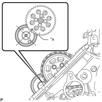
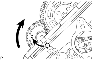
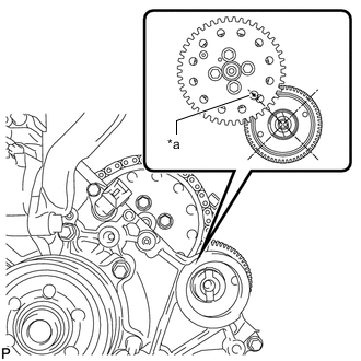
Text in Illustration *a Arrow Rotate the crankshaft clockwise 360° so that the No. 1 camshaft timing sprocket arrow points at the No. 1 camshaft center.
Note
Do not rotate the crankshaft counterclockwise in order to align the sprocket arrow and camshaft center.
-
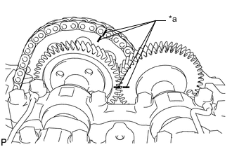
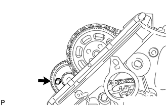
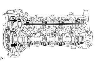
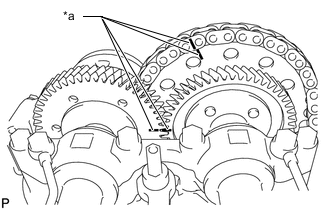
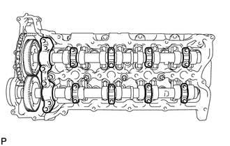
Text in Illustration *a Matchmark Place matchmarks on the No. 1 timing chain and No. 1 camshaft timing sprocket.
-
Place matchmarks on the No. 1 camshaft gear and No. 2 camshaft gear.
-
Using SST, hold the pump drive shaft gear.
- SST
- 09960-10010 ( 09962-01000, 09963-01000 )
-
Remove the 2 bolts and pump drive shaft gear.
-
Disconnect the No. 1 timing chain and No. 1 camshaft timing sprocket from the No. 2 camshaft.
Note
-
Do not remove the No. 1 camshaft timing sprocket from the No. 1 timing chain.
-
Do not rotate the crankshaft until the No. 1 timing chain and No. 1 camshaft timing sprocket are connected to the No. 2 camshaft.
Tech Tips
If fixing the No. 1 camshaft timing sprocket in place, pass a rope or equivalent through one of the No. 1 camshaft timing sprocket holes and tie the No. 1 timing chain and No. 1 camshaft timing sprocket together.
-
-
Turn the No. 1 camshaft clockwise so that the bolt is easier to install.
-
Using a 6 mm x 1.0 pitch service bolt with a length of 16 mm or more, fix the No. 1 camshaft in place.
- Torque:
- 8.0 N*m { 82 kgf*cm, 71 in.*lbf }
Note
Do not drop the bolt into the engine.
Tech Tips
If it is difficult to install the bolt, rotate the No. 1 camshaft so that the bolt is easier to install.
-
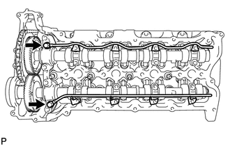
Loosen the 2 union bolts.
-
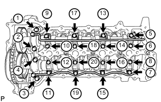
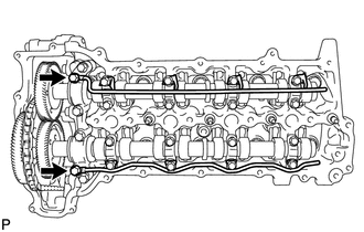
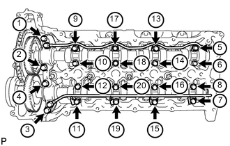
Uniformly loosen and remove the 20 bolts in the sequence shown in the illustration.
-
Remove the 2 union bolts and No. 1 camshaft oil feed pipe sub-assembly and No. 2 camshaft oil feed pipe sub-assembly.
-
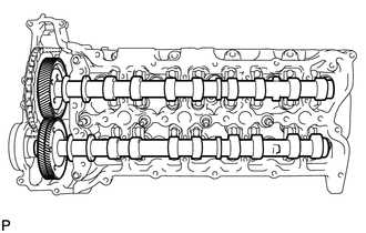
Remove the 8 No. 3 camshaft bearing caps and No. 1 camshaft bearing cap.
Tech Tips
Be sure to arrange the removed parts for each installation position separately.
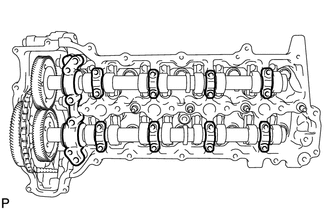
-
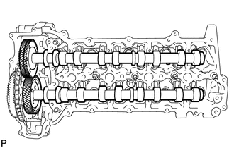
Remove the No. 1 camshaft and No. 2 camshaft.
-
-
REMOVE NO. 3 CAMSHAFT AND NO. 4 CAMSHAFT
-
Text in Illustration *a Arrow Rotate the crankshaft clockwise, and align the No. 2 camshaft timing sprocket arrow with the cylinder head upper surface.
-
Using a 10 mm hexagon wrench, remove the taper screw plug.
-
Fix the No. 2 chain tensioner assembly in place.
-
Push the tensioner slipper away from the No. 2 chain tensioner assembly, and move the stopper plate clockwise to release the lock as shown in A.
-
Push up the tensioner slipper and move the stopper plate counterclockwise to set the lock as shown in B.
-
Push the tensioner slipper away from the No. 2 chain tensioner assembly, and insert a hexagon wrench into the stopper plate hole as shown in C.
Note
Do not drop the hexagon wrench into the engine.
Text in Illustration *a Stopper Plate - -
-
-
Using SST, hold the No. 2 camshaft timing sprocket.
- SST
- 09960-10010 ( 09962-01000, 09963-01000 )
-
Remove the 2 bolts.
-
Text in Illustration *a Arrow Rotate the crankshaft clockwise 360° so that the No. 2 camshaft timing sprocket arrow points at the No. 4 camshaft center.
-
Text in Illustration *a Matchmark Place matchmarks on the No. 2 timing chain and No. 2 camshaft timing sprocket.
-
Place matchmarks on the No. 3 camshaft gear and No. 4 camshaft gear.
-
Using SST, hold the No. 2 camshaft timing sprocket.
- SST
- 09960-10010 ( 09962-01000, 09963-01000 )
-
Remove the 2 bolts, and disconnect the No. 2 timing chain and No. 2 camshaft timing sprocket from the No. 3 camshaft.
Note
-
Do not remove the No. 2 camshaft timing sprocket from the No. 2 timing chain.
-
Do not rotate the crankshaft until the No. 2 timing chain and No. 2 camshaft timing sprocket are connected to the No. 3 camshaft.
Tech Tips
If fixing the No. 2 camshaft timing sprocket in place, pass a rope or equivalent through one of the No. 2 camshaft timing sprocket holes and tie the No. 2 timing chain and No. 2 camshaft timing sprocket together.
-
-
Using a 6 mm x 1.0 pitch service bolt with a length of 16 mm or more, fix the No. 4 camshaft in place.
- Torque:
- 8.0 N*m { 82 kgf*cm, 71 in.*lbf }
Note
Do not drop the bolt into the chain cover.
Tech Tips
If it is difficult to install the bolt, rotate the No. 4 camshaft so that the bolt is easier to install.
-

Loosen the 2 union bolts.
-
Uniformly loosen and remove the 20 bolts in the sequence shown in the illustration.
-
Remove the 2 union bolts and No. 3 camshaft oil feed pipe sub-assembly and No. 4 camshaft oil feed pipe sub-assembly.
-
Remove the 8 No. 3 camshaft bearing caps and No. 4 camshaft bearing cap.
Tech Tips
Be sure to arrange the removed parts for each installation position separately.
-
Remove the No. 3 camshaft and No. 4 camshaft.
-