ENGINE ON-VEHICLE INSPECTION

PROCEDURE
-
INSPECT ENGINE IDLE SPEED
Note
-
Turn all the electrical systems and the A/C off.
-
When checking the idle speed, move the shift lever to neutral.
Tech Tips
-
For more information about the GTS, refer to its operator's manual.
-
If an GTS is not available, use a tachometer tester probe as a substitute.
-
When using the GTS:
-
Warm up the engine.
-
Connect the GTS to the DLC3.
-
Enter the following menus:
Powertrain / Engine / Data List / Engine Speed.
Tech Tips
Refer to the GTS operator's manual for help selecting the Data List.
-
Inspect the engine idle speed.
Standard Idle Speed 550 to 750 rpm -
Disconnect the GTS from the DLC3.
-
-
When not using the GTS:
-
Warm up and stop the engine.
-
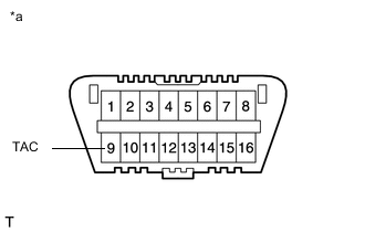
Text in Illustration *a Front view of DLC3 Connect a tester probe of a tachometer to terminal 9 (TAC) of the DLC3 with SST.
- SST
- 09843-18040
-
Inspect the engine idle speed.
Standard Idle Speed 550 to 750 rpm -
Disconnect the tester probe from terminal 9 (TAC) of the DLC3.
-
-
-
INSPECT MAXIMUM ENGINE SPEED
-
Start the engine.
-
Fully depress the accelerator pedal.
-
Check the maximum engine speed.
Maximum engine speed 4700 to 4900 rpm
-
-
INSPECT COMPRESSION
-
Warm up and stop the engine.
-
Disconnect the cable from the negative (-) battery terminal.
-
Remove the No. 1 glow plug connector.
-
Remove the intercooler assembly Click here.
-
Remove the injection pipes Click here.
-
Remove the No. 1 glow plug connector.
-
Reinstall the injection pipes Click here.
-
-
Remove the 8 glow plug assemblies Click here.
-
Disconnect all connectors from the 8 injectors.
-
Connect the cable to the negative (-) battery terminal.
-
Inspect the cylinder compression pressure.
-
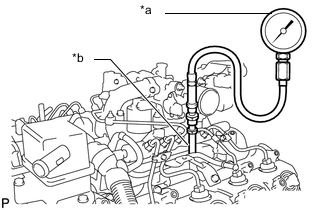
Text in Illustration *a SST (Compression Gauge) *b SST (Attachment) Insert SST (attachment) into the glow plug hole.
- SST
- 09992-00026 ( 09992-00410, 09992-00211 )
- Torque:
- 13 N*m { 133 kgf*cm, 10 ft.*lbf }
-
Connect SST (compression gauge) to SST (attachment).
-
While cranking the engine, measure the compression pressure.
Standard compression pressure (normal condition) 2700 kPa (27.5 kgf/cm2, 392 psi) Minimum compression pressure 2200 kPa (22.4 kgf/cm2, 319 psi) Difference between each cylinder 500 kPa (5.1 kgf/cm2, 73 psi) or less Note
-
Use a fully-charged battery so the engine speed can be increased to 280 rpm or more.
-
Inspect the other cylinders in the same way.
-
Measure the compression as quickly as possible.
-
-
If the cylinder compression is low, pour a small amount of engine oil into the cylinder through the glow plug holes. Then inspect the cylinder compression again.
If adding oil increases the compression pressure, the piston rings and/or cylinder bore may be worn or damaged.
If the pressure stays low, the valve may be stuck or seated improperly, or there may be leakage from the gasket.
-
Remove SST (attachment and compression gauge).
-
-
Disconnect the cable from the negative (-) battery terminal.
-
Connect all connectors to the 8 injectors.
-
Install the 8 glow plug assemblies Click here.
-
Install the No. 1 glow plug connector.
-
Remove the injection pipes Click here.
-
Reinstall the No. 1 glow plug connector.
-
Install the injection pipes Click here.
-
Install the intercooler assembly Click here.
-
-