CYLINDER HEAD GASKET(w/o DPF) INSTALLATION
CAUTION / NOTICE / HINT
Note
-
Before performing these installation procedures, sufficiently clean and remove any foreign matter from the cylinder block sub-assembly, cylinder head, camshaft and other parts.
-
When replacing an injector assembly (including interchanging injector assemblies between cylinders), common rail assembly, cylinder head, or intake manifold, replace the corresponding injection pipes with a new one.
PROCEDURE
-
CHECK INJECTOR COMPENSATION CODE
-
SELECT CYLINDER HEAD GASKET
-
Set the 2 crankshaft pulley set bolts to the crankshaft.
-
Clean the cylinder block sub-assembly with solvent.
-
Inspect the protrusion for each cylinder.
-
Set the piston of the cylinder to be measured to slightly before TDC.
-
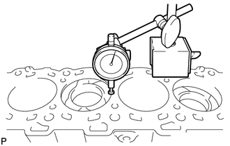
Place a dial indicator on the cylinder block sub-assembly, and set the measuring tip as shown in the illustration.
Note
Make sure that the dial indicator is at a right angle to the cylinder block sub-assembly top surface.
-
Set the dial indicator at 0 mm (0 in.).
Tech Tips
Make sure that the measuring tip is flat against the cylinder block sub-assembly surface and piston head when taking the measurements.
-
Find where the piston head protrudes most by slowly turning the crankshaft clockwise and counterclockwise.
-
Measure the piston protrusion value of each cylinder at 2 places as shown in the illustration below, making a total of 8 measurements.
Standard piston protrusion 0.520 to 0.780 mm (0.0205 to 0.0307 in.) If the protrusion is not as specified, remove and reinstall the piston and connecting rod.
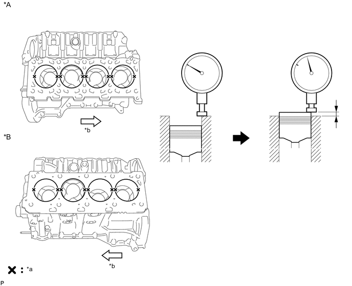
Text in Illustration *A for Bank 1 *B for Bank 2 *a Measuring *b Front
-
-
Select a new cylinder head gasket.
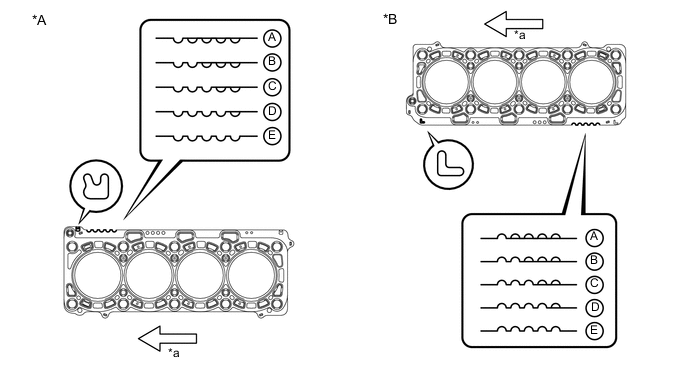
Text in Illustration *A for Bank 1 *B for Bank 2 *a Front - - Tech Tips
Cylinder head gaskets are marked A, B, C, D or E accordingly.
New Installed Cylinder Head Gasket Thickness Item Cutout Specified Condition* A 1 1.20 to 1.30 mm (0.0472 to 0.0512 in.) B 2 1.25 to 1.35 mm (0.0492 to 0.0394 in.) C 3 1.30 to 1.40 mm (0.0512 to 0.0551 in.) D 4 1.35 to 1.45 mm (0.0531 to 0.0571 in.) E 5 1.40 to 1.50 mm (0.0551 to 0.0591 in.) Tech Tips
*: The specified condition indicates the thickness of the cylinder head gasket after tightening the cylinder head.
-
Select the largest piston protrusion value from the measurements and then select a new appropriate cylinder head gasket according to the table below.
Standard Piston Protrusion Item Specified Condition A 0.520 to 0.575 mm (0.0205 to 0.0226 in.) B 0.575 to 0.625 mm (0.0226 to 0.0246 in.) C 0.625 to 0.675 mm (0.0246 to 0.0266 in.) D 0.675 to 0.725 mm (0.0266 to 0.0285 in.) E 0.725 to 0.780 mm (0.0285 to 0.0307 in.)
-
-
-
INSTALL NO. 2 CYLINDER HEAD GASKET
-
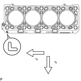
Text in Illustration *a Front *b Exhaust Side Remove any oil from the contact surface.
-
Place the No. 2 cylinder head gasket on the cylinder block sub-assembly surface with the front face of the indicated mark "L" upward and facing the exhaust side.
-
-
INSTALL CYLINDER HEAD GASKET
-
Text in Illustration *a Front *b Exhaust Side Remove any oil from the contact surface.
-
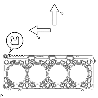
Place the cylinder head gasket on the cylinder block sub-assembly surface with the front face of the indicated mark "R" upward and facing the exhaust side.
-
-
INSTALL CYLINDER HEAD LH
-
INSTALL CYLINDER HEAD SUB-ASSEMBLY
-
SET NO. 1 CYLINDER TO 45° BEFORE TDC
-
INSTALL NO. 2 VALVE LASH ADJUSTER ASSEMBLY
-
INSTALL NO. 1 VALVE LASH ADJUSTER ASSEMBLY
-
INSTALL NO. 2 VALVE ROCKER ARM SUB-ASSEMBLY
-
INSTALL NO. 1 VALVE ROCKER ARM SUB-ASSEMBLY
-
INSTALL NO. 5 CAMSHAFT BEARING CAP
-
INSTALL NO. 2 CAMSHAFT BEARING CAP
-
INSTALL NO. 3 CAMSHAFT AND NO. 4 CAMSHAFT
-
INSTALL NO. 1 CAMSHAFT AND NO. 2 CAMSHAFT
-
INSTALL TIMING GEAR CASE SUB-ASSEMBLY
-
INSTALL V-BANK SILENCER
-
INSTALL FUEL SUPPLY PUMP ASSEMBLY
-
INSTALL FUEL PUMP MOTOR WIRE
-
INSPECT RADIAL BALL BEARING
-
TEMPORARILY INSTALL FUEL SUPPLY PUMP DRIVE GEAR
-
SET NO. 1 CAMSHAFT AND NO. 2 CAMSHAFT TO TDC
-
INSTALL NO. 1 IDLE GEAR SHAFT
-
INSTALL IDLE GEAR ASSEMBLY
-
TIGHTEN FUEL SUPPLY PUMP DRIVE GEAR NUT
-
CHECK NO. 1 CYLINDER TO TDC/COMPRESSION
-
INSTALL NO. 2 CAMSHAFT TIMING SPROCKET AND NO. 2 TIMING CHAIN
-
INSTALL NO. 1 CAMSHAFT TIMING SPROCKET AND NO. 1 TIMING CHAIN
-
INSTALL PUMP DRIVE SHAFT GEAR
-
INSTALL NO. 2 CHAIN VIBRATION DAMPER
-
INSTALL NO. 2 CHAIN TENSIONER SLIPPER
-
INSTALL NO. 2 CHAIN TENSIONER ASSEMBLY
-
INSTALL NO. 1 CHAIN VIBRATION DAMPER
-
INSTALL NO. 1 CHAIN TENSIONER SLIPPER
-
INSTALL NO. 1 CHAIN TENSIONER ASSEMBLY
-
INSTALL NO. 1 CRANKSHAFT POSITION SENSOR PLATE
-
CHECK NO. 1 CYLINDER TO TDC/COMPRESSION
-
INSTALL FRONT CRANKSHAFT OIL SEAL
-
INSTALL TIMING CHAIN COVER SUB-ASSEMBLY
-
TEMPORARILY INSTALL INTAKE MANIFOLD
-
TEMPORARILY INSTALL COMMON RAIL ASSEMBLY RH
-
TEMPORARILY INSTALL COMMON RAIL ASSEMBLY LH
-
INSTALL FUEL INJECTOR RH
-
INSTALL FUEL INJECTOR LH
-
REMOVE COMMON RAIL ASSEMBLY RH
-
REMOVE COMMON RAIL ASSEMBLY LH
-
REMOVE INTAKE MANIFOLD
-
INSTALL NOZZLE HOLDER GASKET LH
-
INSTALL CYLINDER HEAD COVER SUB-ASSEMBLY LH
-
INSTALL NOZZLE HOLDER SEAL LH
-
INSTALL OIL SEPARATOR ASSEMBLY
-
INSTALL NOZZLE HOLDER GASKET RH
-
INSTALL CYLINDER HEAD COVER SUB-ASSEMBLY
-
INSTALL NOZZLE HOLDER SEAL RH
-
INSTALL CYLINDER HEAD COVER SILENCER LH
-
INSTALL CYLINDER HEAD COVER SILENCER RH
-
INSTALL VACUUM PUMP ASSEMBLY
-
INSTALL NO. 1 VACUUM TRANSMITTING PIPE SUB-ASSEMBLY
-
INSTALL NO. 1 VACUUM SWITCHING VALVE ASSEMBLY
-
INSTALL GLOW PLUG ASSEMBLY
-
INSTALL NO. 1 GLOW PLUG CONNECTOR
-
INSTALL WATER OUTLET PIPE
-
INSTALL WATER OUTLET
-
INSTALL NO. 2 INTERCOOLER SUPPORT BRACKET
-
INSTALL STARTER HOSE BRACKET
-
Install the starter hose bracket with the 2 bolts.
- Torque:
- 10 N*m { 102 kgf*cm, 7 ft.*lbf }
-
-
INSTALL STARTER ASSEMBLY
-
INSTALL ENGINE WATER PUMP ASSEMBLY
-
CONNECT INLET WATER HOSE
-
INSTALL NO. 2 IDLER PULLEY BRACKET (w/ Viscous Heater)
-
INSTALL NO. 2 IDLER PULLEY (w/ Viscous Heater)
-
INSTALL FAN BRACKET SUB-ASSEMBLY
-
INSTALL TIMING GEAR COVER INSULATOR
-
INSTALL THERMOSTAT
-
INSTALL WATER INLET
-
INSTALL NO. 1 IDLER PULLEY BRACKET (w/ Viscous Heater)
-
INSTALL VISCOUS WITH MAGNET CLUTCH HEATER ASSEMBLY (w/ Viscous Heater)
-
INSTALL CRANKSHAFT POSITION SENSOR
-
INSTALL CAMSHAFT POSITION SENSOR
-
INSTALL NO. 1 OIL PAN SUB-ASSEMBLY
-
INSTALL OIL STRAINER SUB-ASSEMBLY
-
INSTALL NO. 2 OIL PAN SUB-ASSEMBLY
-
INSTALL ENGINE OIL LEVEL SENSOR
-
INSTALL OIL FILTER BRACKET SUB-ASSEMBLY
-
INSTALL OIL FILTER ELEMENT
-
INSTALL TIMING GEAR COVER SPACER
-
INSTALL CRANKSHAFT PULLEY
-
CONNECT NO. 2 OIL COOLER HOSE
-
CONNECT NO. 1 OIL COOLER HOSE
-
INSTALL V-RIBBED BELT TENSIONER ASSEMBLY
-
INSTALL STIFFENER INSULATOR RH
-
INSTALL COMPRESSOR BRACKET
-
INSTALL NO. 2 CYLINDER BLOCK INSULATOR
-
INSTALL ENGINE MOUNTING BRACKET LH
-
INSTALL NO. 2 WATER BY-PASS PIPE SUB-ASSEMBLY
-
INSTALL NO. 3 VACUUM TRANSMITTING PIPE SUB-ASSEMBLY
-
INSTALL TURBOCHARGER WIRE
-
INSTALL NO. 2 INTAKE AIR CONNECTOR BRACKET
-
INSTALL NO. 1 CYLINDER BLOCK INSULATOR
-
INSTALL ENGINE MOUNTING BRACKET RH
-
INSTALL NO. 4 VACUUM TRANSMITTING PIPE SUB-ASSEMBLY
-
INSTALL NO. 1 WATER BY-PASS PIPE SUB-ASSEMBLY
-
INSTALL AIR TUBE SUPPORT
-
INSTALL NO. 1 INTAKE AIR CONNECTOR BRACKET
-
INSTALL GENERATOR ASSEMBLY
-
INSTALL TURBOCHARGER SUB-ASSEMBLY WITH EXHAUST MANIFOLD AND NO. 2 TURBOCHARGER SUB-ASSEMBLY WITH NO. 2 EXHAUST MANIFOLD
-
CONNECT CABLE TO NEGATIVE BATTERY TERMINAL
Note
When disconnecting the cable, some systems need to be initialized after the cable is reconnected Click here.
-
Connect the cables to the negative (-) main battery and sub-battery terminals.
-