ENGINE ASSEMBLY INSTALLATION

PROCEDURE
-
INSTALL FRONT NO. 2 ENGINE MOUNTING BRACKET LH
-
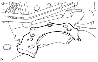
Install the engine mounting bracket LH with the bolt.
- Torque:
- 32 N*m { 326 kgf*cm, 24 ft.*lbf }
-
-
INSTALL FRONT ENGINE MOUNTING INSULATOR RH
-
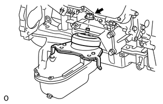
Install the mounting insulator with the nut.
- Torque:
- 72 N*m { 734 kgf*cm, 53 ft.*lbf }
-
-
INSTALL FRONT ENGINE MOUNTING INSULATOR LH
-
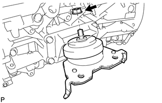
Install the mounting insulator with the nut.
- Torque:
- 72 N*m { 734 kgf*cm, 53 ft.*lbf }
-
-
REMOVE ENGINE STAND
-
Install 2 engine hangers with 2 bolts as shown in the illustration.
- Torque:
- 43 N*m { 438 kgf*cm, 32 ft.*lbf }
Tech Tips
Item Part No. Engine hanger 12281-38150 Bolt 90119-14120 -
Attach an engine sling device and hang the engine with a chain block.
-
Remove the bolts and engine assembly from the engine stand.
Note
-
With the exception of installing the engine assembly to an engine stand or removing the engine assembly from an engine stand, do not perform any work on the engine while it is suspended, as doing so is dangerous.
-
Pay attention to the angle of the sling device as the engine assembly or engine hangers may be damaged or deformed if the angle is incorrect.
-
-
-
INSTALL ENGINE ASSEMBLY
-
Slowly lower the engine assembly into the engine compartment.
Note
Make sure that the engine is clear of all wiring and hoses.
-
Attach the engine mounting insulators to the vehicle.
-
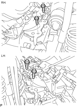
Install the 4 engine mounting insulator bolts.
- Torque:
- 79 N*m { 806 kgf*cm, 58 ft.*lbf }
-
Remove the 2 bolts and 2 engine hangers.
-
-
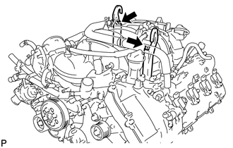
INSTALL WATER PIPE AND HOSE SUB-ASSEMBLY
-
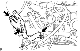
Connect the hose and install the water pipe and hose with the 2 bolts.
- Torque:
- 18 N*m { 184 kgf*cm, 13 ft.*lbf }
-
-
CONNECT OIL COOLER PIPE ASSEMBLY
-
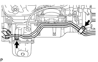
Connect the oil cooler pipe with the 2 bolts.
- Torque:
- 14 N*m { 143 kgf*cm, 10 ft.*lbf }
-
-
INSTALL DRIVE PLATE AND RING GEAR SUB-ASSEMBLY
-
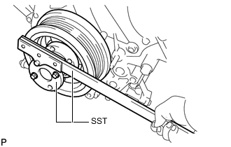
Using SST, hold the crankshaft.
- SST
- 09213-70011
- 09330-00021
-
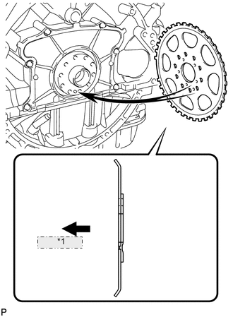
*1 Engine Side Install the crankshaft angle sensor rotor.
Tech Tips
-
Align the pin hole of the crankshaft angle sensor rotor with the pin of the crankshaft.
-
As the crankshaft angle sensor rotor is not reversible, be sure to install it so that it is facing in the direction shown in the illustration.
-
-
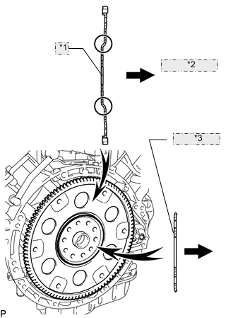
*1 Drive Plate *2 Automatic Transmission Side *3 Rear Drive Plate Spacer Install the drive plate and rear drive plate spacer onto the crankshaft.
Tech Tips
As the rear drive plate spacer and the drive plate are not reversible, be sure to install them so that they are facing in the direction shown in the illustration.
-
Install the drive plate and ring gear and bolts.
Tech Tips
The bolts are tightened in 2 progressive steps.
-
Clean the bolts and bolt holes.
-
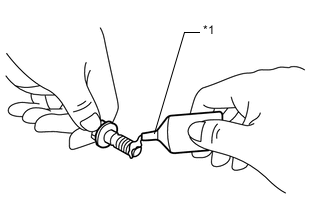
*1 Adhesive Apply adhesive to 2 or 3 threads at the end of each of the 10 bolts.
Adhesive Toyota Genuine Adhesive 1324, Three Bond 1324 or equivalent -
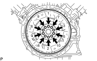
Step 1:
Install and uniformly tighten 10 new bolts in the sequence shown in the illustration.
- Torque:
- 30 N*m { 301 kgf*cm, 22 ft.*lbf }
Note
-
Do not reuse the flywheel installation bolts.
-
Do not strike or damage the flywheel installation bolts. Be sure to handle them carefully.
-
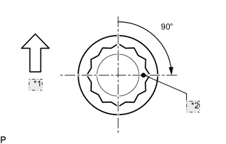
*1 Up *2 Painted Mark Mark the upside of each flywheel installation bolt with paint.
-
Step 2:
Tighten the flywheel installation bolts 90° as shown in the illustration.
-
Check that the painted marks are now at a 90° angle to the upside.
Note
Do not start the engine for at least an hour after installing the drive plate.
-
-
-
INSTALL REAR NO. 1 ENGINE MOUNTING INSULATOR
-
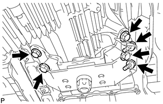
Install the rear engine mounting insulator to the transmission with the 4 bolts.
- Torque:
- 59 N*m { 602 kgf*cm, 44 ft.*lbf }
-
Install the front engine mounting insulator RH with the 2 bolts.
- Torque:
- 12 N*m { 122 kgf*cm, 9 ft.*lbf }
-
-
INSTALL AUTOMATIC TRANSMISSION ASSEMBLY
-
INSTALL STARTER ASSEMBLY
-
INSTALL STARTER COVER
-
INSTALL EXHAUST MANIFOLD SUB-ASSEMBLY RH
-
INSTALL NO. 1 EXHAUST MANIFOLD HEAT INSULATOR
-
INSTALL NO. 1 MANIFOLD STAY
-
INSTALL EXHAUST MANIFOLD SUB-ASSEMBLY LH
-
INSTALL NO. 2 EXHAUST MANIFOLD HEAT INSULATOR
-
INSTALL NO. 2 MANIFOLD STAY
-
INSTALL PROPELLER SHAFT HEAT INSULATOR
-
INSTALL REAR PROPELLER SHAFT ASSEMBLY
-
INSTALL FRONT PROPELLER SHAFT ASSEMBLY
-
INSTALL FRONT EXHAUST PIPE ASSEMBLY
-
INSTALL FRONT NO. 2 EXHAUST PIPE ASSEMBLY
-
INSTALL CENTER EXHAUST PIPE ASSEMBLY
-
INSTALL TAILPIPE ASSEMBLY
-
INSTALL ENGINE OIL LEVEL DIPSTICK GUIDE
-
INSTALL GENERATOR ASSEMBLY
-
for 150A Type:
-
for 180A Type:
-
-
CONNECT VANE PUMP ASSEMBLY
-
CONNECT COOLER COMPRESSOR ASSEMBLY
-
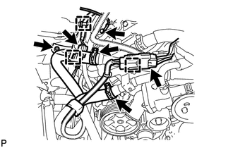
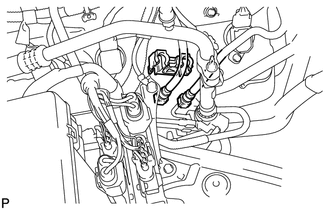
CONNECT WIRE HARNESS AND HOSE
-
Connect the 2 clamps and 2 connectors.
-
Connect the 2 connectors and 2 clips to the engine room junction block.
-
Install the engine wire with the nut. Then connect the 2 clips.
- Torque:
- 10 N*m { 102 kgf*cm, 7 ft.*lbf }
-
w/ Secondary Air Injection System:
Connect the 4 air injection control driver connectors.
-
Connect the ground wire and clamp to the body with the bolt.
- Torque:
- 8.4 N*m { 86 kgf*cm, 74 in.*lbf }
-
Connect the cable to the positive (+) battery terminal.
-
Install the wire to the positive (+) battery cable with the nut.
- Torque:
- 5.4 N*m { 55 kgf*cm, 48 in.*lbf }
-
w/ Secondary Air Injection System:
Connect the 2 air injection system hoses.
-
Install the ground wire with the bolt.
- Torque:
- 8.0 N*m { 82 kgf*cm, 71 in.*lbf }
-
w/ Secondary Air Injection System:
Connect the 3 clamps and 2 air pump connectors.
-
w/ Secondary Air Injection System:
Install the connector bracket with the nut.
- Torque:
- 8.0 N*m { 82 kgf*cm, 71 in.*lbf }
-
Connect the connectors.
-
for RHD:
Connect the 4 connectors and 2 clips to the connector holder block.
-
for LHD:
Connect the 5 connectors and clip to the connector holder block.
-
-
Connect the ECM connector.
-
for RHD:
Connect the 2 clamps and ECM connector.
Tech Tips
Refer to the following procedures to connect the ECM connector Click here.
-
for LHD:
Connect the clamp and ECM connector.
Tech Tips
Refer to the following procedures to connect the ECM connector Click here.
-
-
Connect the purge line hose.
-
-
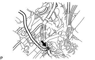
CONNECT FUEL MAIN AND RETURN HOSE
-
Connect the fuel main and return hoses Click here.
-
Install the fuel pipe clamp.
-
-
INSTALL WATER HOSE SUB-ASSEMBLY
-
INSTALL RADIATOR ASSEMBLY
-
INSTALL FAN SHROUD
-
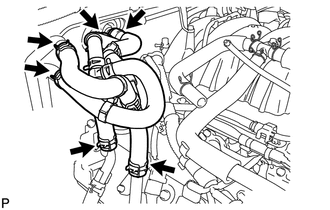
INSTALL NO. 2 RADIATOR HOSE
-
INSTALL NO. 1 RADIATOR HOSE
-
INSTALL AIR CLEANER ASSEMBLY
-
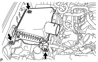
Install the air cleaner with the 3 bolts.
- Torque:
- 5.0 N*m { 51 kgf*cm, 44 in.*lbf }
-
-
INSTALL AIR CLEANER HOSE ASSEMBLY
-
INSTALL HOOD SUB-ASSEMBLY
-
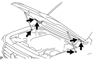
Install the hood with the 4 bolts.
- Torque:
- 13 N*m { 133 kgf*cm, 10 ft.*lbf }
-
Connect the 2 hood supports with the 2 hood support bolts.
- Torque:
- 18 N*m { 184 kgf*cm, 13 ft.*lbf }
CAUTION:
Install the hood support while supporting the hood by hand.
Note
Check that the hood support is engaged in the ball joint and that it cannot be pulled out.
-
-
ADJUST HOOD SUB-ASSEMBLY
-
INSTALL COWL TOP VENTILATOR LOUVER SUB-ASSEMBLY
-
INSTALL HOOD TO COWL TOP SEAL
-
INSTALL FRONT FENDER MAIN SEAL LH
-
INSTALL FRONT FENDER MAIN SEAL RH
-
INSTALL FRONT WIPER ARM LH
-
INSTALL FRONT WIPER ARM RH
-
INSTALL RADIATOR SIDE DEFLECTOR LH
-
INSTALL TRANSMISSION OIL COOLER AIR DUCT
-
INSTALL FRONT FENDER APRON SEAL REAR RH
-
INSTALL FRONT FENDER APRON SEAL FRONT RH
-
INSTALL FRONT FENDER APRON SEAL REAR LH
-
INSTALL FRONT FENDER APRON SEAL FRONT LH
-
INSTALL OIL PAN PROTECTOR ASSEMBLY
-
INSTALL NO. 2 ENGINE UNDER COVER
-
INSTALL NO. 1 ENGINE UNDER COVER SUB-ASSEMBLY
-
ADD ENGINE OIL
-
ADD ENGINE COOLANT
-
CONNECT CABLE TO NEGATIVE BATTERY TERMINAL
Note
When disconnecting the cable, some systems need to be initialized after the cable from the cable is reconnected Click here.
-
INSPECT FOR OIL LEAK
-
INSPECT FOR COOLANT LEAK
-
INSPECT FOR EXHAUST GAS LEAK
-
INSPECT FOR FUEL LEAK
-
INSPECT SHIFT LEVER POSITION
-
INSPECT IGNITION TIMING
-
INSPECT ENGINE IDLE SPEED
-
INSPECT CO/HC
-
INSPECT ENGINE OIL LEVEL
-
INSPECT ENGINE COOLANT LEVEL
-
INSTALL V-BANK COVER SUB-ASSEMBLY
-
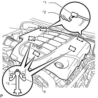
*1 Bracket *2 Hook *3 Pin *4 Grommet Attach the 2 V-bank cover hooks to the bracket. Then align the 3 V-bank cover grommets with the 3 pins, and press down on the V-bank cover to attach the pins.
-
-
INSTALL FRONT BUMPER COVER