RELAY ON-VEHICLE INSPECTION
PROCEDURE
-
INSPECT FUEL PUMP RELAY (SUB PUMP)
-
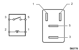
Measure the resistance according to the value(s) in the table below.
Standard Resistance Tester Connection Condition Specified Condition 3 - 5 Battery voltage is not applied to terminals 1 and 2 10 kΩ or higher Battery voltage is applied to terminals 1 and 2 Below 1 Ω If the result is not as specified, replace the fuel pump relay.
-
-
INSPECT EDU RELAY (EDU1)
-
Measure the resistance according to the value(s) in the table below.
Standard Resistance Tester Connection Condition Specified Condition 3 - 5 Battery voltage is not applied between 1 and 2 10 kΩ or higher Battery voltage is applied between 1 and 2 Below 1 Ω If the result is not as specified, replace the EDU relay.
-
-
INSTALL EDU RELAY (EDU2)
-
Measure the resistance according to the value(s) in the table below.
Standard Resistance Tester Connection Condition Specified Condition 3 - 5 Battery voltage is not applied between 1 and 2 10 kΩ or higher Battery voltage is applied between 1 and 2 Below 1 Ω If the result is not as specified, replace the EDU relay.
-
-
INSPECT NO. 1 IGNITION RELAY (IG1)
-
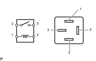
Measure the resistance according to the value(s) in the table below.
Standard Resistance Tester Connection Condition Specified Condition 3 - 5 Battery voltage not applied to terminals 1 and 2 10 kΩ or higher Battery voltage applied to terminals 1 and 2 Below 1 Ω If the result is not as specified, replace the No. 1 ignition relay.
-
-
INSPECT INTEGRATION RELAY (AIR FUEL RATIO SENSOR RELAY) (w/ DPF)
-
Measure the resistance of the A/F HTR fuse.
-
Measure the resistance according to the value(s) in the table below.
Standard Resistance Tester Connection Condition Specified Condition A/F HTR fuse Always Below 1 Ω If the result is not as specified, replace the A/F HTR fuse.
-
-
Measure the resistance of the ignition relay air fuel ratio sensor relay circuit.
-
Measure the resistance according to the value(s) in the table below.
Standard Resistance Tester Connection Condition Specified Condition 1M-1 - 1Q-3 Battery voltage is not applied to terminals 1Q-2 and 1Q-4 10 kΩ or higher Battery voltage is applied to terminals 1Q-2 and 1Q-4 Below 1 Ω 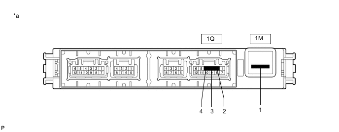
Text in Illustration *a Component without harness connected
(Integration Relay)
- - If the result is not as specified, replace the integration relay.
-
-
-
INSPECT INTEGRATION RELAY (IG2 MAIN RELAY)
-
Measure the resistance of the IG2 MAIN fuse.
-
Measure the resistance according to the value(s) in the table below.
Standard Resistance Tester Connection Condition Specified Condition IG2 MAIN fuse Always Below 1 Ω If the result is not as specified, replace the IG2 MAIN fuse.
-
-
Measure the resistance of the IG2 main relay circuit.
-
Measure the resistance according to the value(s) in the table below.
Standard Resistance Tester Connection Condition Specified Condition 1M-1 - 1P-1 Battery voltage is not applied to terminals 1P-2 and 1Q-4 10 kΩ or higher Battery voltage is applied to terminals 1P-2 and 1Q-4 Below 1 Ω 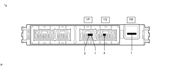
Text in Illustration *a Component without harness connected
(Integration Relay)
- - If the result is not as specified, replace the integration relay.
-
-
-
INSPECT INTEGRATION RELAY (EFI MAIN NO.1 RELAY)
-
Measure the resistance of the EFI MAIN NO. 1 fuse and EFI NO. 2 fuse.
-
Measure the resistance according to the value(s) in the table below.
Standard Resistance Tester Connection Condition Specified Condition EFI MAIN NO. 1 fuse Always Below 1 Ω EFI NO. 2 fuse Always Below 1 Ω If the result is not as specified, replace the EFI MAIN NO. 1 fuse and/or EFI NO. 2 fuse.
-
-
Measure the resistance of the EFI MAIN No. 1 relay circuit.
-
Measure the resistance according to the value(s) in the table below.
Standard Resistance Tester Connection Condition Specified Condition 1M-1 - 1Q-1 Battery voltage is not applied to terminals 1Q-8 and 1Q-4 10 kΩ or higher Battery voltage is applied to terminals 1Q-8 and 1Q-4 Below 1 Ω 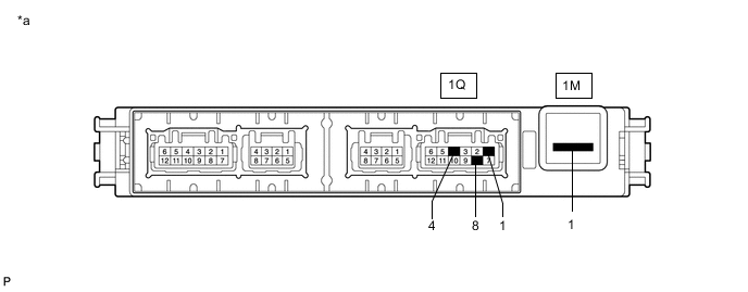
Text in Illustration *a Component without harness connected
(Integration Relay)
- - If the result is not as specified, replace the integration relay.
-
-
-
INSPECT INTEGRATION RELAY (EFI MAIN NO. 2 RELAY)
-
Measure the resistance of the EFI MAIN NO. 2 fuse.
-
Measure the resistance according to the value(s) in the table below.
Standard Resistance Tester Connection Condition Specified Condition EFI MAIN NO. 2 fuse Always Below 1 Ω If the result is not as specified, replace the EFI MAIN NO. 2 fuse.
-
-
Measure the resistance of the EFI MAIN No. 2 relay circuit.
-
Measure the resistance according to the value(s) in the table below.
Standard Resistance Tester Connection Condition Specified Condition 1M-1 - 1N-12 Battery voltage is not applied to terminals 1N-8 and 1N-11 10 kΩ or higher Battery voltage is applied to terminals 1N-8 and 1N-11 Below 1 Ω 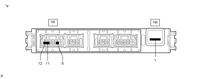
Text in Illustration *a Component without harness connected
(Integration Relay)
- - If the result is not as specified, replace the integration relay.
-
-
-
INSPECT MAIN BODY ECU (IG1 NO. 1)
-
Measure the resistance of the ECU-IG NO. 2 fuse.
-
Measure the resistance according to the value(s) in the table below.
Standard Resistance Tester Connection Condition Specified Condition ECU-IG NO. 2 fuse Always Below 1 Ω If the result is not as specified, replace the ECU-IG NO. 2 fuse.
-
-
Measure the resistance of the IG1 No. 1 relay circuit.
-
Measure the resistance according to the value(s) in the table below.
Standard Resistance Tester Connection Condition Specified Condition 2G-1 - 2H-24 Battery voltage not applied between 2I-18 and 2J-1 10 kΩ or higher Battery voltage applied between 2I-18 and 2J-1 Below 1 Ω 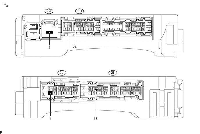
Text in Illustration *a Component without harness connected
Main Body ECU (Cowl Side Junction Block LH)
- - If the result is not as specified, replace the main body ECU.
-
-
-
INSPECT STARTER RELAY (ST)
-
INSPECT NO. 1 GLOW RELAY (GLOW NO. 1)
-
INSPECT NO. 2 GLOW RELAY (GLOW NO. 2)
-
INSPECT MAIN BODY ECU (ACC RELAY)