ECD SYSTEM(w/o DPF) ECM Power Source Circuit
DESCRIPTION
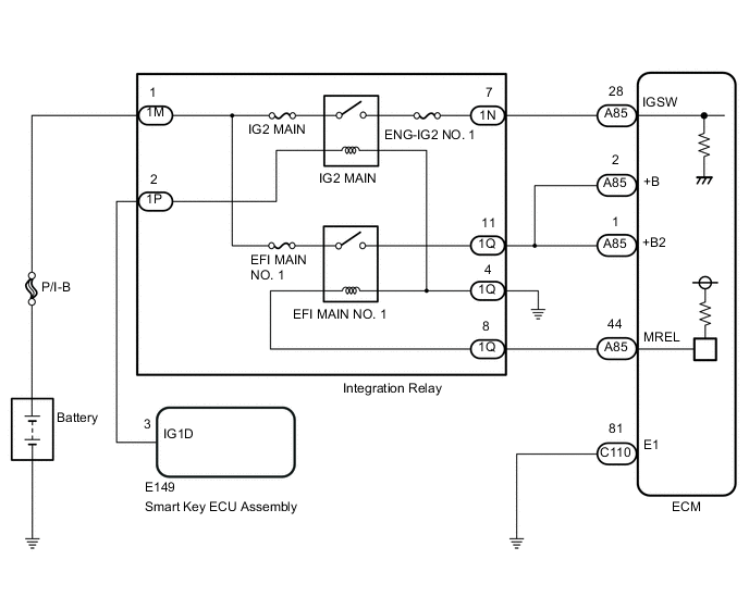
When the engine switch is turned on (IG), the battery voltage is applied to the IGSW terminal of the ECM. The output signal from the MREL terminal of the ECM causes current to flow to the coil, closing the contacts of the integration relay (EFI relay) and supplying power to terminal +B of the ECM.
WIRING DIAGRAM
CAUTION / NOTICE / HINT
Note
After replacing the ECM, the new ECM needs registration (See page ) and initialization Click here.
PROCEDURE
-
INSPECT INTEGRATION RELAY (POWER SOURCE)
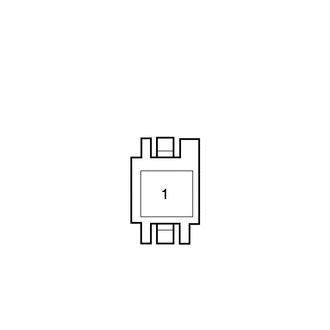
*a Front view of wire harness connector
(Integration relay)
-
Remove the integration relay from the engine room relay block.
-
Measure the voltage according to the value(s) in the table below.
Standard Voltage Tester Connection Condition Specified Condition 1M-1 - Body ground Always 11 to 14 V
NG 
REPAIR OR REPLACE HARNESS OR CONNECTOR
OK 
-
-
CHECK HARNESS AND CONNECTOR (INTEGRATION RELAY - BODY GROUND)
-
Remove the integration relay from the engine room relay block.
-
Measure the resistance according to the value(s) in the table below.
Standard Resistance Tester Connection Condition Specified Condition 1Q-4 - Body ground Always Below 1 Ω
NG
REPAIR OR REPLACE HARNESS OR CONNECTOR
OK
-
-
INSPECT INTEGRATION RELAY (EFI MAIN NO. 1 AND IG2 MAIN)
-
Inspect the integration relay Click here.
NG
REPLACE INTEGRATION RELAY
OK
-
-
CHECK HARNESS AND CONNECTOR (INTEGRATION RELAY - ECM)
-
Remove the integration relay from the engine room relay block.
-
Disconnect the ECM connector.
-
Measure the resistance according to the value(s) in the table below.
Standard Resistance Tester Connection Condition Specified Condition A85-44 (MREL) - 1Q-8 Always Below 1 Ω A85-2 (+B) - 1Q-11 Always Below 1 Ω A85-1 (+B2) - 1Q-11 Always Below 1 Ω A85-44 (MREL) or 1Q-8 - Body ground Always 10 kΩ or higher A85-2 (+B) or 1Q-11 - Body ground Always 10 kΩ or higher A85-1 (+B2) or 1Q-11 - Body ground Always 10 kΩ or higher
NG
REPAIR OR REPLACE HARNESS OR CONNECTOR
OK
-
-
CHECK HARNESS AND CONNECTOR (ECM - BODY GROUND)
-
Disconnect the ECM connector.
-
Measure the resistance according to the value(s) in the table below.
Standard Resistance Tester Connection Condition Specified Condition C110-81 - Body ground Always Below 1 Ω
NG
REPAIR OR REPLACE HARNESS OR CONNECTOR
OK
-
-
INSPECT ECM (IGSW VOLTAGE)
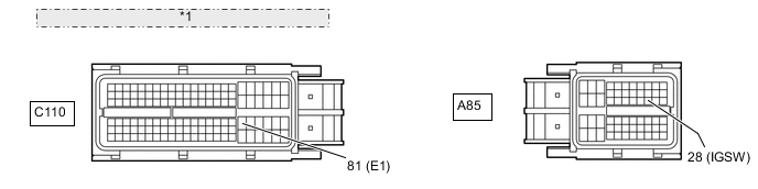
*1 Front view of wire harness connector: (to ECM)
-
Disconnect the ECM connectors.
-
Turn the engine switch on (IG).
-
Measure the voltage according to the value(s) in the table below.
Standard Voltage Tester Connection Switch Condition Specified Condition A85-28 (IGSW) - C110-81 (E1) Engine switch on (IG) 11 to 14 V
OK
REPLACE ECM Click here
NG
-
-
CHECK HARNESS AND CONNECTOR (INTEGRATION RELAY - ECM)
-
Disconnect the ECM connector.
-
Remove the integration relay from the engine room relay block.
-
Measure the resistance according to the value(s) in the table below.
Standard Resistance Tester Connection Condition Specified Condition A85-28 (IGSW) - 1N-7 Always Below 1 Ω A85-28 (IGSW) or 1N-7 - Body ground Always 10 kΩ or higher Result Result Proceed to OK (w/ Entry and Start System) A OK (w/o Entry and Start System) B NG C
B
REPAIR OR REPLACE HARNESS OR CONNECTOR
A
-
-
CHECK HARNESS AND CONNECTOR (SMART KEY ECU ASSEMBLY - INTEGRATION RELAY)
-
Disconnect the smart key ECU assembly connector.
-
Disconnect the integration relay connector.
-
Measure the resistance according to the value(s) in the table below.
Standard Resistance Tester Connection Condition Specified Condition E149-3 (IG1D) - 1P-2 Always Below 1 Ω E149-3 (IG1D) or 1P-2 - Body ground Always 10 kΩ or higher
OK
CHECK SMART KEY SYSTEM
NG
REPAIR OR REPLACE HARNESS OR CONNECTOR
-