ECD SYSTEM(w/o DPF) Fuel Injection System
CAUTION / NOTICE / HINT
Note
-
After replacing the ECM, the new ECM needs registration (See page ) and initialization Click here.
-
After replacing the fuel supply pump assembly, the ECM needs initialization Click here.
-
After replacing an injector assembly, the ECM needs registration Click here.
PROCEDURE
-
CHECK INJECTOR COMPENSATION CODE
-
Check the injector compensation code Click here.
Result Result Proceed to Except below A Compensation codes of the installed injector assemblies are the same as the compensation codes registered in the ECM B
B 
TAKE SNAPSHOT DURING IDLING AND 4000 RPM (PROCEDURE 3) Click here
A 
-
-
REGISTER INJECTOR COMPENSATION CODE
-
Register the injector compensation codes Click here.
NEXT
-
-
TAKE SNAPSHOT DURING IDLING AND 4000 RPM (PROCEDURE 3)
-
Connect the GTS to the DLC3.
-
Start the engine and turn the GTS on.
-
Enter the following menus: Engine and ECT / Data List / Common Rail.
-
Take a snapshot of the Data List items.
Tech Tips
-
A snapshot can be used to compare vehicle data from the time of the malfunction to normal data and is very useful for troubleshooting. The data in the list below is that of a normal vehicle, but as the data varies between individual vehicles, this data should only be used for reference.
-
Check the Data List at idling and at 4000 rpm with no load after the engine is warmed up.
-
NEXT
-
-
READ VALUE USING GTS (INJECTION FEEDBACK VAL #1 TO #8 AND INJECTION VOLUME)
-
Check Injection Feedback Val #1 to #8 and Injection Volume in the snapshot taken in procedure 3 when the engine was idling and at 4000 rpm with no load.
Result Result Proceed to Injection Feedback Val for at least one cylinder is more than 3.0 mm3/st
A Injection Volume is 10 mm3/st or less at 4000 rpm
B Except above C Tech Tips
-
When there is a problem with the operation of an injector assembly due to foreign matter in the inside of the injector assembly, etc., the fuel injection volume decreases. As a result, the ECM gives instructions to increase the fuel injection volume, which causes Injection Feedback Val to increase.
-
The ECM controls the system so that the sum of Injection Feedback Val for all of the cylinders is approximately 0 mm3/st. Even if the value of Injection Feedback Val for a cylinder is less than -3.0 mm3/st (-3.0 mm3/st is the lowest normal value), as long as the value of Injection Feedback Val for each of the other cylinders is 3.0 mm3/st or less, the injector assemblies are not malfunctioning.
-
B
REPLACE INJECTOR ASSEMBLIES OF ALL CYLINDERS Click here
C
READ VALUE USING GTS (INJECTION VOLUME) Click here
A
-
-
PERFORM ACTIVE TEST USING GTS (CHECK THE CYLINDER COMPRESSION)
Tech Tips
Use this Active Test to help determine whether a cylinder has compression loss or not.
-
Connect the GTS to the DLC3.
-
Start the engine and turn the GTS on.
-
Enter the following menus: Engine and ECT / Active Test / Check the Cylinder Compression / Data List / Compression / Engine Speed of Cyl #1 to #8.
-
Check the engine speed during the Active Test.
Result Result Proceed to Except below A The values of Engine Speed Cyl #1 to #8 are within +/-10 rpm of each other. B Tech Tips
When cranking, if the speed of a cylinder is approximately 100 rpm more than the other cylinders, there is probably a complete loss of compression in that cylinder.
B
READ VALUE USING GTS (INJECTION FEEDBACK VAL #1 TO #8) Click here
A
-
-
CHECK CYLINDER COMPRESSION PRESSURE
-
Check the cylinder compression pressure Click here.
Tech Tips
When compression is low, there may be cracks in the piston or the injector assembly may be installed improperly.
NG
CHECK AND REPLACE ENGINE ASSEMBLY Click here
OK
-
-
READ VALUE USING GTS (INJECTION FEEDBACK VAL #1 TO #8)
-
Connect the GTS to the DLC3.
-
Turn the engine switch on (IG) and turn the GTS on.
-
Start the engine and warm it up.
-
Enter the following menus: Engine and ECT / Data List / Injection Feedback Val #1 to #8.
-
Read the values.
Standard GTS Display Engine Condition* Normal Value Injection Feedback Val #1 to #8 Idling -3.0 mm3/st to 3.0 mm3/st
Tech Tips
*: The A/C switch and all accessory switches should be off, the engine coolant temperature should be 75°C (167°F) or more and the engine should be idled for 1 minute or more.
Result Result Proceed to Injection Feedback Val for at least one cylinder is more than 3.0 mm3/st
A Except above B Tech Tips
-
When there is a problem with the operation of an injector assembly due to foreign matter in the inside of the injector assembly, etc., the fuel injection volume decreases. As a result, the ECM gives instructions to increase the fuel injection volume, which causes Injection Feedback Val to increase.
-
The ECM controls the system so that the sum of Injection Feedback Val for all of the cylinders is approximately 0 mm3/st. Even if the value of Injection Feedback Val for a cylinder is less than -3.0 mm3/st (-3.0 mm3/st is the lowest normal value), as long as the value of Injection Feedback Val for each of the other cylinders is 3.0 mm3/st or less, the injector assemblies are not malfunctioning.
-
B
PERFORM ACTIVE TEST USING GTS (TEST THE FUEL LEAK) Click here
A
-
-
REPLACE INJECTOR ASSEMBLY OF MALFUNCTIONING CYLINDER
-
Replace the injector assembly of the malfunctioning cylinder Click here.
Note
-
When replacing the injector assembly for a cylinder, always be sure to use a new injection pipe.
-
Follow the procedure in the repair manual and temporarily install the injection pipes and nozzle leakage pipe, and then correctly position the injector assemblies. After that, tighten parts according to the torque specifications.
-
If the installation procedure is not performed correctly, injector assemblies may become out of position, which may cause the injector assemblies to deteriorate, resulting in malfunctions.
-
If an injector assembly deteriorates and malfunctions, other problems such as knocking, rough idle, etc. may occur.
-
If an injector assembly becomes out of position, it is possible that the seal between the injector assembly and injection pipe may become incomplete, resulting in a fuel leak.
-
NEXT
CLEAN FUEL FILTER CASE AND REPLACE FUEL FILTER Click here
-
-
READ VALUE USING GTS (INJECTION VOLUME)
-
Check Injection Volume in the snapshot taken in procedure 3 when the engine was idling.
Result Result Proceed to Injection Volume while idling after engine warm up is 12 mm3/st or more
A Except above B
B
PERFORM ACTIVE TEST USING GTS (TEST THE FUEL LEAK) Click here
A
-
-
REPLACE INJECTOR ASSEMBLIES OF ALL CYLINDERS
-
Replace the injector assemblies of all cylinders Click here.
Note
-
When replacing the injector assembly for a cylinder, always be sure to use a new injection pipe.
-
Follow the procedure in the repair manual and temporarily install the injection pipes and nozzle leakage pipe, and then correctly position the injector assemblies. After that, tighten parts according to the torque specifications.
-
If the installation procedure is not performed correctly, injector assemblies may become out of position, which may cause the injector assemblies to deteriorate, resulting in malfunctions.
-
If an injector assembly deteriorates and malfunctions, other problems such as knocking, rough idle, etc. may occur.
-
If an injector assembly becomes out of position, it is possible that the seal between the injector assembly and injection pipe may become incomplete, resulting in a fuel leak.
-
NEXT
-
-
CLEAN FUEL FILTER CASE AND REPLACE FUEL FILTER
-
Clean the fuel filter case and replace the fuel filter.
Tech Tips
Be sure to clean the inside of the fuel filter case as the fuel injectors may not operate properly if the fuel filter is installed with foreign matter remaining inside the fuel filter case.
NEXT
-
-
BLEED AIR FROM FUEL SYSTEM
-
Bleed the air from the fuel system Click here.
NEXT
-
-
REGISTER INJECTOR COMPENSATION CODE
-
Register the injector compensation codes Click here.
NEXT
PERFORM ACTIVE TEST USING GTS (TEST THE FUEL LEAK) Click here
-
-
CHECK AND REPLACE ENGINE ASSEMBLY
-
Check and replace the engine assembly.
NEXT
-
-
PERFORM ACTIVE TEST USING GTS (TEST THE FUEL LEAK)
-
Connect the GTS to the DLC3.
-
Turn the engine switch on (IG) and turn the GTS on.
-
Enter the following menus: Engine and ECT / Active Test / Test the Fuel Leak / Data List / Common Rail Pressure, Target Common Rail Pressure, and Target Pump SCV Current.
-
Start the engine.
-
Take a snapshot with the GTS during the Active Test.
-
Measure the difference between the target fuel pressure (Target Common Rail Pressure) and the actual fuel pressure (Common Rail Pressure) when the "Test the Fuel Leak" Active Test is performed.
Tech Tips
In order to obtain an exact measurement, perform the Active Test 5 times and measure the difference once each time the Active Test is performed.
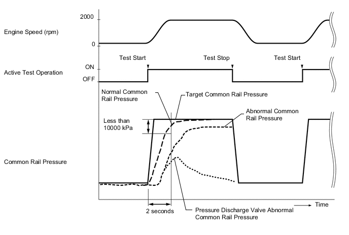
OK The difference between the target fuel pressure and the actual fuel pressure 2 seconds after the Active Test starts is less than 10000 kPa (102.0 kgf/cm2, 1451 psi). Result Result Proceed to NG A OK* B Note
*: Even when the results of the Active Test are normal, take a snapshot of vehicle data when the vehicle is accelerating. If "Common Rail Pressure" does not follow "Target Common Rail Pressure", proceed to step 16.
If "Common Rail Pressure" does not follow "Target Common Rail Pressure", the fuel filter may be clogged.
Tech Tips
-
"Target Common Rail Pressure" means target fuel pressure controlled by the ECM.
-
"Common Rail Pressure" means actual fuel pressure in common rail assembly.
-
If the pressure discharge valve mounted on the common rail assembly is malfunctioning, the actual fuel pressure may change as indicated by "Pressure Discharge Valve Malfunctioning" in the illustration.
-
The pressure discharge valve operates to discharge fuel pressure when the internal pressure of the common rail exceeds the target fuel pressure.
-
B
READ VALUE USING GTS (COMMON RAIL PRESSURE AND TARGET COMMON RAIL PRESSURE) Click here
A
-
-
INSPECT CLOGGED FUEL PIPE
-
Connect the GTS to the DLC3.
-
Start the engine and turn the GTS on.
-
Enter the following menus: Engine and ECT / Data List / Diesel Injection.
-
With no load after the engine is warmed up, take a snapshot when idling and when the vehicle is accelerating with the accelerator pedal fully depressed in 2nd gear.
-
Check the Target Common Rail Pressure and Fuel Press value.
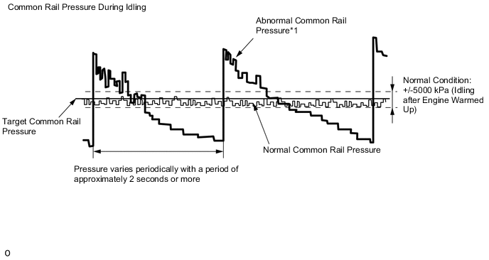
Result Result Proceed to While idling the vehicle, "Common Rail Pressure" deviates from the normal range and varies periodically with a period of approximately 2 seconds or more*1 A "Common Rail Pressure" is normal while idling the vehicle, but "Fuel Press" does not follow "Target Common Rail Pressure" when the accelerator pedal is fully depressed in 2nd gear*2 Except above B Note
-
*1: The cause may be a squashed or blocked fuel pipe or hose.
-
*2: The cause may be a clogged fuel filter.
-
B
REPLACE FUEL SUPPLY PUMP ASSEMBLY (SUCTION CONTROL VALVE) Click here
A
-
-
REPAIR OR REPLACE CLOGGED FUEL LINE
-
Repair or replace the clogged (including frozen fuel) fuel pipe.
-
Replace the fuel filter element sub-assembly.
Tech Tips
If "Common Rail Pressure" does not follow "Target Common Rail Pressure" when the accelerator pedal is fully depressed in 2nd gear, replace the fuel filter element sub-assembly.
NEXT
-
-
BLEED AIR FROM FUEL SYSTEM
-
Bleed the air from the fuel system Click here.
NEXT
-
-
READ VALUE USING GTS (COMMON RAIL PRESSURE AND TARGET COMMON RAIL PRESSURE)
-
Check Common Rail Pressure and Target Common Rail Pressure in the snapshot taken in procedure 3 when the engine was idling.
Result Result Proceed to Difference between Common Rail Pressure and Target Common Rail Pressure is 5000 kPa (51.0 kgf/cm2, 725 psi) or more
B Except above A
A 
END
B
-
-
REPLACE FUEL SUPPLY PUMP ASSEMBLY (SUCTION CONTROL VALVE)
-
Replace the fuel supply pump assembly Click here.
NEXT
-
-
BLEED AIR FROM FUEL SYSTEM
-
Bleed the air from the fuel system Click here.
NEXT
-
-
PERFORM SUPPLY PUMP INITIALIZATION
-
Perform supply pump initialization Click here.
NEXT
-
-
CONFIRM WHETHER MALFUNCTION HAS BEEN SUCCESSFULLY REPAIRED
NEXT
END