AUTOMATIC HIGH BEAM SYSTEM TERMINALS OF ECU
-
CHECK COWL SIDE JUNCTION BLOCK LH AND MAIN BODY ECU (MULTIPLEX NETWORK BODY ECU)
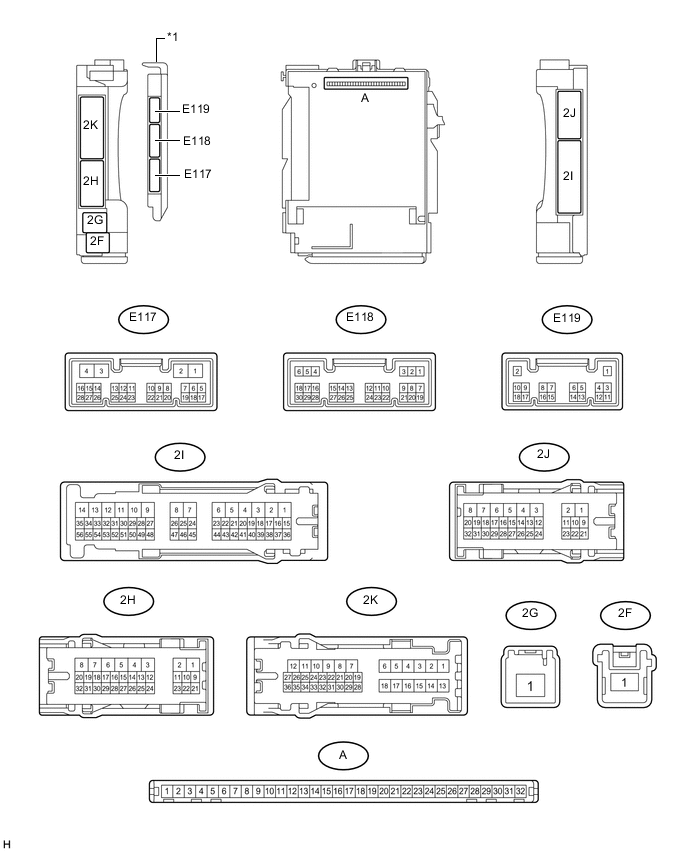
Text in Illustration *1 Main Body ECU (Multiplex Network Body ECU) - -
-
Measure the voltage and check for pulses according to the value(s) in the table below.
Terminal No. (Symbol) Wiring Color Terminal Description Condition Specified Condition E118-1 (DIM) - Body ground B - Body ground High beam headlight drive output Dimmer switch in high or high flash position Below 1 V Dimmer switch in low position 11 to 14 V E117-23 (AHBI) - Body ground L - Body ground Auto high beam switch signal input Auto high beam switch on Below 1 V Auto high beam switch off 11 to 14 V E118-24 (HU) - Body ground V - Body ground Dimmer switch high position signal input Dimmer switch in high position Below 1 V Dimmer switch not in high position Pulse generation E118-19 (CLTB) - E118-21 (CLTE) GR - W Automatic light control sensor power supply output Engine switch off Below 1 V Engine switch on (IG), light control switch in AUTO position 11 to 14 V E118-20 (CLTS) - Body ground R - Body ground Automatic light control sensor signal input Engine switch off Below 1 V Automatic light control system operating Communication waveform generation
(See waveform 1)
E118-8 (A) - Body ground P - Body ground Light control switch AUTO position signal input Light control switch in AUTO position Below 1 V Light control switch not in AUTO position Pulse generation If the result is not as specified, the main body ECU (multiplex network body ECU) or cowl side junction block LH may be malfunctioning.
-
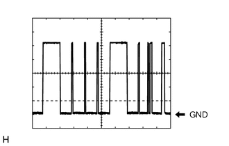
Waveform 1
Item Content Tool setting 5 V/DIV., 10 ms/DIV. Tech Tips
The communication waveform changes according to the surrounding brightness.
-
-
-
INNER REAR VIEW MIRROR ASSEMBLY (w/o Pre-crash Safety System)

-
Disconnect the R13 mirror connector.
-
Measure the voltage and resistance according to the value(s) in the table below.
Terminal No. (Symbol) Wiring Color Terminal Description Condition Specified Condition R13-1 (IG) - Body ground B - Body ground IG power supply Engine switch on (IG) 11 to 14 V R13-2 (E) - Body ground W-B - Body ground Ground Always Below 1 Ω R13-9 (CANH) - Body ground G - Body ground CAN communication line Engine switch on (IG) Pulse generation R13-10 (CANL) - Body ground B - Body ground CAN communication line Engine switch on (IG) Pulse generation
-
-
FORWARD RECOGNITION CAMERA (w/ Pre-crash Safety System) Click here.