LIGHTING SYSTEM Taillight Relay Circuit
DESCRIPTION
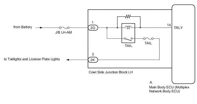
The main body ECU (multiplex network body ECU) receives headlight dimmer switch information signals and illuminates the taillights and license plate lights.
WIRING DIAGRAM
CAUTION / NOTICE / HINT
Note
-
Inspect the fuses for circuits related to this system before performing the following inspection procedure.
-
w/ Door Control Battery:
The vehicle battery supplies power to the main body ECU (multiplex network body ECU) via the door control battery. Therefore, before proceeding with troubleshooting, perform an on-vehicle inspection and confirm that the main body ECU (multiplex network body ECU) power source circuit is normal Click here.
-
If the main body ECU (multiplex network body ECU) is replaced, refer to the Service Bulletin.
PROCEDURE
-
PERFORM ACTIVE TEST USING GTS (TAILLIGHT RELAY)
-
Using the GTS, perform the Active Test Click here.
Main Body Tester Display Test Part Control Range Diagnostic Note Taillight Relay Taillight relay ON/OFF - OK Taillight relay operates. (Taillights illuminate.)
OK 
PROCEED TO NEXT SUSPECTED AREA SHOWN IN PROBLEM SYMPTOMS TABLE Click here
NG 
-
-
CHECK HARNESS AND CONNECTOR (COWL SIDE JUNCTION BLOCK LH - BATTERY AND BODY GROUND)
-
Disconnect the 2G cowl side junction block LH connector.
-
Measure the voltage according to the value(s) in the table below.
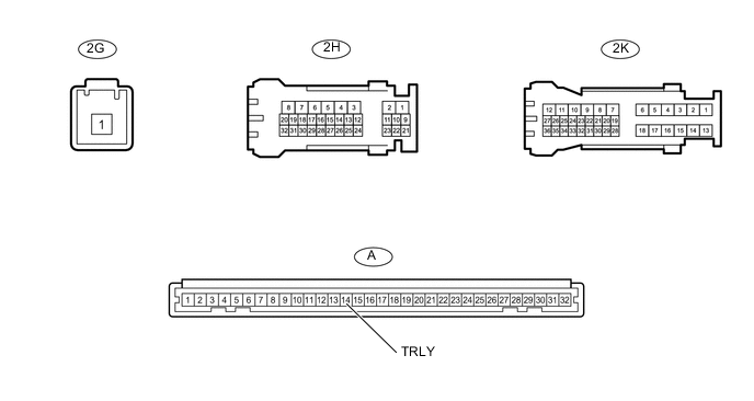
Standard Voltage Tester Connection Condition S5Dcified Condition 2G-1 - Body ground Always 11 to 14 V
NG
REPAIR OR REPLACE HARNESS OR CONNECTOR
OK
-
-
INSPECT COWL SIDE JUNCTION BLOCK LH
-
Remove the cowl side junction block LH.
-
for LHD: Click here
-
for RHD: Click here
-
-
Remove the main body ECU (multiplex network body ECU) from the cowl side junction block LH.
-
for LHD: Click here
-
for RHD: Click here
-
-
Measure the resistance according to the value(s) in the table below.
Standard Resistance Tester Connection Condition Specified Condition 2G-1 - 2K-3 Always 10 kΩ or higher -
Measure the voltage according to the value(s) in the table below.
Standard Voltage Tester Connection Condition Specified Condition 2K-3 - Battery negative (-) Battery voltage applied between terminals 2G-1 and A-14 (TRLY) 11 to 14 V Result Result Proceed to OK (for LHD) A OK (for RHD) B NG (for LHD) C NG (for RHD) D
A
REPLACE MAIN BODY ECU (MULTIPLEX NETWORK BODY ECU) Click here
B
REPLACE MAIN BODY ECU (MULTIPLEX NETWORK BODY ECU) Click here
C
REPLACE COWL SIDE JUNCTION BLOCK LH Click here
D
REPLACE COWL SIDE JUNCTION BLOCK LH Click here
-