LIGHTING SYSTEM Front Fog Light Circuit
DESCRIPTION
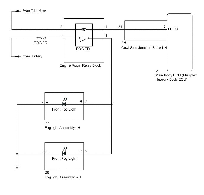
The main body ECU (multiplex network body ECU) receives headlight dimmer switch information signals and illuminates the front fog lights.
WIRING DIAGRAM
CAUTION / NOTICE / HINT
Note
-
Inspect the bulbs and fuses for circuits related to this system before performing the following inspection procedure.
-
w/ Door Control Battery:
As the door control battery is installed between the vehicle battery and main body ECU (multiplex network body ECU), first perform the inspections in On-Vehicle Inspection to confirm that there are no malfunctions in the power source circuit for the main body ECU (multiplex network body ECU) before performing this troubleshooting procedure Click here.
-
If the main body ECU (multiplex network body ECU) is replaced, refer to the Service Bulletin.
PROCEDURE
-
CHECK TAIL LIGHT OPERATION
-
Check for tail and stop light assembly illuminate condition.
OK Tail and stop light assembly operate normally
NG 
PROCEED TO NEXT SUSPECTED AREA SHOWN IN PROBLEM SYMPTOMS TABLE Click here
OK 
-
-
PERFORM ACTIVE TEST USING GTS (FRONT FOG LIGHT RELAY)
-
Using the GTS, perform the Active Test Click here.
Main Body Tester Display Test Part Control Range Diagnostic Note Front Fog Light Relay Front fog light relay ON/OFF The headlight dimmer switch is in the tail position. OK Front fog lights come on.
OK
PROCEED TO NEXT SUSPECTED AREA SHOWN IN PROBLEM SYMPTOMS TABLE Click here
NG
-
-
INSPECT FOG LIGHT ASSEMBLY (FOG FR)
-
Remove the fog light relay (FOG FR) from the engine room relay block.
-
Inspect the fog light relay (FOG FR) Click here.
NG
REPLACE FOG LIGHT RELAY (FR FOG)
OK
-
-
CHECK HARNESS AND CONNECTOR (POWER SOURCE - FOR LIGHT RELAY [FOG FR])
-
Remove the fog light relay (FOG FR) from the engine room relay block.
-
Measure the voltage according to the value(s) in the table below.
Standard Voltage Tester Connection Condition Specified Condition Relay terminal 5 - Body ground Always 11 to 14 V Relay terminal 2 - Body ground Dimmer switch in off Below 1 V Relay terminal 2 - Body ground Dimmer switch in TAIL or HEAD 11 to 14 V
NG
REPAIR OR REPLACE HARNESS OR CONNECTOR
OK
-
-
CHECK HARNESS AND CONNECTOR (FOR LIGHT RELAY [FOG FR] - FOR LIGHT ASSEMBLY)
-
Remove the fog light relay (FOG FR) from the engine room relay block.
-
Disconnect the B7 fog light assembly LH connector.
-
Disconnect the B8 fog light assembly RH connector.
-
Measure the resistance according to the value(s) in the table below.
Standard Resistance Tester Connection Condition Specified Condition Relay terminal 3 - B7-2 (B) Always Below 1 Ω Relay terminal 3 - Body ground Always 10 kΩ or higher B7-2 (B) - Body ground Always 10 kΩ or higher
NG
REPAIR OR REPLACE HARNESS OR CONNECTOR
OK
-
-
CHECK HARNESS AND CONNECTOR (FOR LIGHT RELAY [FOG FR] - COWL SIDE JUNCTION BLOCK LH)
-
Remove the fog light relay (FOG FR) from the engine room relay block.
-
Disconnect the 2H cowl side junction LH connector.
-
Measure the resistance according to the value(s) in the table below.
Standard Resistance Tester Connection Condition Specified Condition Relay terminal 1 - 2H-31 Always Below 1 Ω Relay terminal 1 - Body ground Always 10 kΩ or higher 2H-31 - Body ground Always 10 kΩ or higher
NG
REPAIR OR REPLACE HARNESS OR CONNECTOR
OK
-
-
INSPECT COWL SIDE JUNCTION BLOCK LH
-
for LHD:
-
Remove the cowl side junction block LH Click here.
-
Remove the main body ECU (multiplex network body ECU) from the cowl side junction block LH Click here.
-
-
for RHD:
-
Remove the cowl side junction block LH Click here.
-
Remove the main body ECU (multiplex network body ECU) from the cowl side junction block LH Click here.
-
-
Measure the resistance according to the value(s) in the table below.
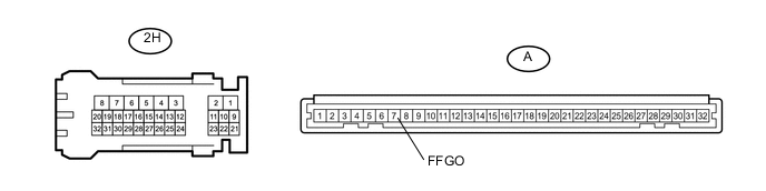
Standard Resistance Tester Connection Condition Specified Condition 2H-31 - A-7 (FFGO) Always Below 1 Ω Result Result Proceed to OK (for LHD) A OK (for RHD) B NG (for LHD) C NG (for RHD) D
A
REPLACE MAIN BODY ECU (MULTIPLEX NETWORK BODY ECU) Click here
B
REPLACE MAIN BODY ECU (MULTIPLEX NETWORK BODY ECU) Click here
C
REPLACE COWL SIDE JUNCTION BLOCK LH Click here
D
REPLACE COWL SIDE JUNCTION BLOCK LH Click here
-