LIGHTING SYSTEM, Diagnostic DTC:U0242
| DTC Code | DTC Name |
|---|---|
| U0242 | Lost Communication With Headlamp Control Module "B" |
DESCRIPTION
This DTC is output when a headlight ECU sub-assembly RH internal malfunctioning or the communication malfunction between headlight ECU sub-assembly LH and headlight ECU sub-assembly RH is 10 seconds or more.
The headlight ECU sub-assembly LH outputs DTC U0242.
| DTC Code | DTC Detection Condition | Trouble Area |
|---|---|---|
| U0242 | Either conditions:
|
|
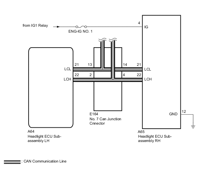
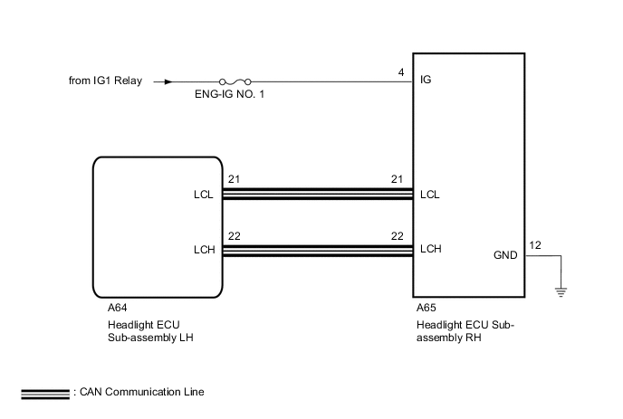
WIRING DIAGRAM
-
w/ Adaptive High Beam System
-
w/o Adaptive High Beam System
CAUTION / NOTICE / HINT
Note
If the headlight ECU sub-assembly LH has been replaced, it is necessary to synchronize the vehicle information Click here.
PROCEDURE
-
CLEAR DTC
-
Clear the DTCs Click here.
NEXT 
-
-
CHECK FOR DTC
-
Turn the engine switch on (IG).
-
Turn on the headlights using the headlight dimmer switch.
-
Check for DTCs Click here.
OK DTC U0242 are not output. Result Result Proceed to OK A NG (w/ Adaptive High Beam System) B NG (w/o Adaptive High Beam System) (for LHD) C NG (w/o Adaptive High Beam System) (for RHD) D
A 
USE SIMULATION METHOD TO CHECK Click here
C
GO TO CAN COMMUNICATION SYSTEM Click here
D
GO TO CAN COMMUNICATION SYSTEM Click here
B
-
-
CHECK HARNESS AND CONNECTOR (HEADLIGHT ECU SUB-ASSEMBLY LH - NO. 7 CAN JUNCTION CONNECTOR
-
Cable disconnected from negative (-) battery terminal
-
Disconnect the E164 No. 7 CAN junction connector.
-
Measure the resistance according to the value(s) in the table below.
Standard Resistance Tester Connection Condition Specified Condition E164-13 - E164-3 Cable disconnected from negative (-) battery terminal Below 1 Ω E164-14 - E164-4 Cable disconnected from negative (-) battery terminal 10 kΩ or higher
NG 
HARNESS AND CONNECTOR (HEADLIGHT ECU SUB-ASSEMBLY - NO. 7 CAN JUNCTION CONNECTOR Click here
OK
-
-
CHECK HEADLIGHT ECU SUB-ASSEMBLY RH - POWERSOURCE AND BODY GROUND)
-
Cable disconnected from negative (-) battery terminal
-
Disconnect the A65 headlight ECU sub-assembly RH connector.
-
Measure the voltage according to the value(s) in the table below.
Standard Voltage Tester Connection Condition Specified Condition A65-4 (IG) - Body ground Engine switch on (IG) 11 to 14 V -
Measure the resistance according to the value(s) in the table below.
Standard Resistance Tester Connection Condition Specified Condition A65-12 (GND) - Body ground Always Below 1 Ω
NG
REPAIR OR REPLACE HARNESS OR CONNECTOR
OK
-
-
REPLACE HEADLIGHT ECU SUB-ASSEMBLY RH
-
Replace the headlight ECU sub-assembly RH with a new or normally functioning one Click here.
-
Turn the engine switch on (IG).
-
Turn on the headlights using the headlight dimmer switch.
-
Clear the DTCs Click here.
-
Check for DTCs Click here.
OK
END (HEADLIGHT ECU SUB-ASSEMBLY RH WAS DEFECTIVE)
NG
-
-
CHECK FOR DTC
-
Reconnect the E164 No. 7 CAN junction connector.
-
Turn the engine switch on (IG).
-
Turn on the headlights using the headlight dimmer switch.
-
Clear the DTCs Click here.
-
Check for DTCs Click here.
OK DTC U0242 are not output.
OK
USE SIMULATION METHOD TO CHECK Click here
NG
REPLACE HEADLIGHT ECU SUB-ASSEMBLY LH Click here
-
-
HARNESS AND CONNECTOR (HEADLIGHT ECU SUB-ASSEMBLY - NO. 7 CAN JUNCTION CONNECTOR
-
Reconnect the E164 No. 7 CAN junction connector.
-
Disconnect the A64 headlight ECU sub-assembly LH connector.
-
Disconnect the A65 headlight ECU sub-assembly RH connector.
-
Measure the resistance according to the value(s) in the table below.
Standard Resistance Tester Connection Condition Specified Condition A64-22 (LCH ) - A64-21 (LCL) Cable disconnected from negative (-) battery terminal 54 to 69 Ω A64-22 (LCH ) - A64-21 (LCL) Cable disconnected from negative (-) battery terminal 54 to 69 Ω
OK
CHECK HEADLIGHT ECU SUB-ASSEMBLY LH Click here
NG
REPAIR OR REPLACE HARNESS OR CONNECTOR
-