ADAPTIVE HIGH BEAM SYSTEM Adaptive High Beam Switch Circuit
DESCRIPTION
The headlight ECU sub-assembly detects combination switch assembly (adaptive high beam switch) signals. The adaptive high beam system can be turned on and off by operating the combination switch assembly (adaptive high beam switch).
WIRING DIAGRAM
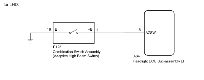
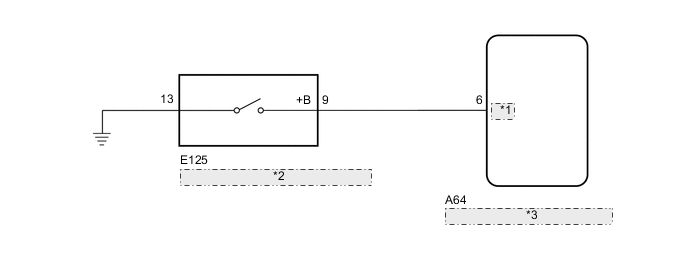
| *1 | AZSW |
| *2 | Combination Switch Assembly (Adaptive High Beam Switch) |
| *3 | Headlight ECU Sub-assembly LH |
CAUTION / NOTICE / HINT
Note
If the headlight ECU sub-assembly LH has been replaced, it is necessary to synchronize the vehicle information Click here.
PROCEDURE
-
READ VALUE USING GTS
-
Connect the GTS to the DLC3.
-
Turn the engine switch on (IG).
-
Turn the GTS on.
-
Enter the following menus: Body Electrical / AFS / Data List.
-
Read the Data List according to the display on the GTS.
AFS Tester Display Measurement Item/Range Normal Condition Diagnostic Note AHS Switch Combination switch assembly (adaptive high beam switch) signal / ON or OF ON: Combination switch assembly (adaptive high beam switch) is operated
OFF: Combination switch assembly (adaptive high beam switch) is not operated
- OK Normal conditions listed above are displayed.
OK 
PROCEED TO NEXT SUSPECTED AREA SHOWN IN PROBLEM SYMPTOMS TABLE Click here
NG 
-
-
INSPECT COMBINATION SWITCH ASSEMBLY (ADAPTIVE HIGH BEAM SWITCH)
-
Remove the combination switch assembly Click here.
-
Inspect the combination switch assembly Click here.
NG
REPLACE COMBINATION SWITCH ASSEMBLY Click here
OK
-
-
CHECK HARNESS AND CONNECTOR (COMBINATION SWITCH ASSEMBLY - HEADLIGHT ECU SUB-ASSEMBLY BODY ECU) AND BODY GROUND)
-
Disconnect the E152 combination switch assembly connector.
-
Disconnect the A64 headlight ECU sub-assembly connector.
-
Measure the resistance according to the value(s) in the table below.
Standard Resistance for LHD Tester Connection Condition Specified Condition A64-6 (AZSW) - E125-1 (+B) Always Below 1 Ω E125-16 (E) - Body ground Always Below 1 Ω A64-6 (AZSW) or E125-1 (+B) - Body ground Always 10 kΩ or higher for RHD Tester Connection Condition Specified Condition A64-6 (AZSW) - E125-9 (+B) Always Below 1 Ω E125-13 (E) - Body ground Always Below 1 Ω A64-6 (AZSW) or E125-9 (+B) - Body ground Always 10 kΩ or higher
OK
REPLACE HEADLIGHT ECU SUB-ASSEMBLY LH Click here
NG
REPAIR OR REPLACE HARNESS OR CONNECTOR
-