ECD SYSTEM(w/ DPF), Diagnostic DTC:P1626, P1627, P1629, P162A
| DTC Code | DTC Name |
|---|---|
| P1626 | Idle Signal Output Value Too Low |
| P1627 | Idle Signal Output Value Too High |
| P1629 | Idol Signal Output Value Too Low Bank2 |
| P162A | Idol Signal Output Value Too High Bank2 |
DESCRIPTION
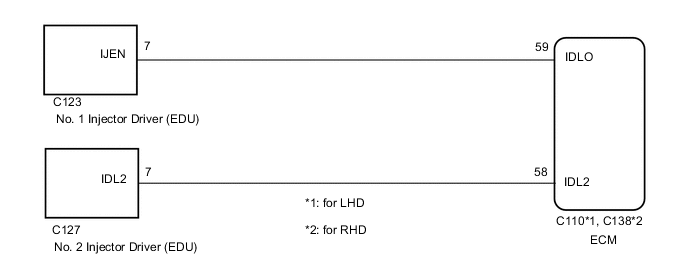
The ECM reduces injector assembly operation speed and applied voltage to the injector assembly to reduce the sound it produces during idling. To do this, the ECM outputs applied voltage switching signals to terminal IJEN of the injector driver from terminal IDLO and IDL2 of the ECM.
| DTC Detection Drive Pattern | DTC Detection Condition | Trouble Area |
|---|---|---|
| Warm up the engine and idle it for 5 seconds | With the engine running at idle, voltage of the ECM IDLO or IDL2 terminal is 0.05 V or less for 5 seconds or more (1 trip detection logic). |
|
| DTC Detection Drive Pattern | DTC Detection Condition | Trouble Area |
|---|---|---|
| Warm up the engine and idle it for 5 seconds | With the engine running at speeds higher than idle, voltage of the ECM IDLO or IDL2 terminal is 3.4 V or higher for 5 seconds or more (1 trip detection logic). |
|
WIRING DIAGRAM
CAUTION / NOTICE / HINT
Note
-
After replacing the ECM, the new ECM needs registration (See page ) and initialization Click here.
-
After replacing the fuel supply pump assembly, the ECM needs initialization Click here.
-
After replacing an injector assembly, the ECM needs registration Click here.
Tech Tips
Read freeze frame data using the GTS. Freeze frame data records the engine condition when malfunctions are detected. When troubleshooting, freeze frame data can help determine if the vehicle was moving or stationary, if the engine was warmed up or not, and other data from the time the malfunction occurred.
PROCEDURE
-
CHECK HARNESS AND CONNECTOR (INJECTOR DRIVER - ECM)
-
Disconnect the No. 1 or No. 2 injector driver connector.
-
Disconnect the ECM connector.
-
Measure the resistance according to the value(s) in the table below.
Standard Resistance for LHD Tester Connection Condition Specified Condition C123-7 (IJEN) - C110-59 (IDLO) Always Below 1 Ω C127-7 (IDL2) - C110-58 (IDL2) Always Below 1 Ω C123-7 (IJEN) or C110-59 (IDLO) - Body ground Always 10 kΩ or higher C127-7 (IDL2) or C110-58 (IDL2) - Body ground Always 10 kΩ or higher Standard Resistance for RHD Tester Connection Condition Specified Condition C123-7 (IJEN) - C138-59 (IDLO) Always Below 1 Ω C127-7 (IDL2) - C138-58 (IDL2) Always Below 1 Ω C123-7 (IJEN) or C138-59 (IDLO) - Body ground Always 10 kΩ or higher C127-7 (IDL2) or C138-58 (IDL2) - Body ground Always 10 kΩ or higher -
Reconnect the No. 1 or No. 2 injector driver connector.
-
Reconnect the ECM connector.
NG 
REPAIR OR REPLACE HARNESS OR CONNECTOR Click here
OK 
-
-
REPLACE INJECTOR DRIVER
-
When DTC P1626 or P1627 is output:
Replace the No. 1 injector driver Click here.
-
When DTC P1629 or P162A is output:
Replace the No. 2 injector driver Click here.
NEXT
-
-
CHECK ANY OTHER DTCS OUTPUT
-
Connect the GTS to the DLC3.
-
Turn the engine switch on (IG) and turn the GTS on.
-
Enter the following menus: Engine and ECT / Trouble Codes.
-
Read the DTCs.
Result Result Proceed to No DTC is output A P1626 or P1627 is output B
A 
END
B
-
-
REPLACE ECM
-
Replace the ECM Click here.
NEXT
CONFIRM WHETHER MALFUNCTION HAS BEEN SUCCESSFULLY REPAIRED Click here
-
-
REPAIR OR REPLACE HARNESS OR CONNECTOR
-
Repair or replace the harness or connector.
NEXT
-
-
CONFIRM WHETHER MALFUNCTION HAS BEEN SUCCESSFULLY REPAIRED
-
Connect the GTS to the DLC3.
-
Clear the DTCs Click here.
-
After warming up the engine, idle the engine for 5 seconds or more.
-
Enter the following menus: Engine and ECT / Trouble Codes.
-
Confirm that the DTC is not output again.
NEXT
END
-