SFI SYSTEM, Diagnostic DTC:P0412, P0415
| DTC Code | DTC Name |
|---|---|
| P0412 | Secondary Air Injection System Switching Valve "A" Circuit |
| P0415 | Secondary Air Injection System Switching Valve "B" Circuit |
DESCRIPTION
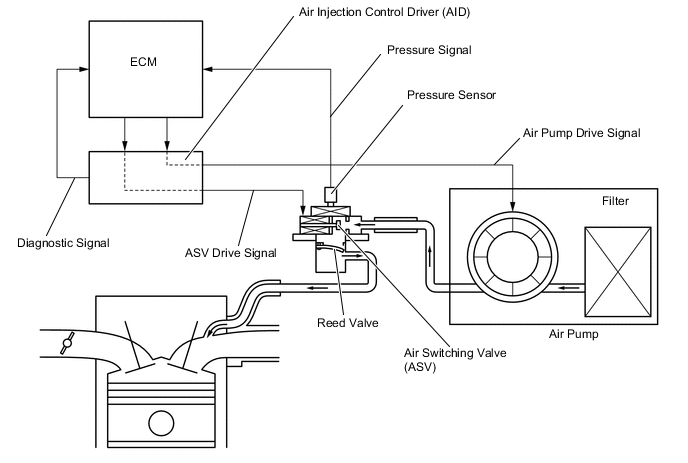
The Secondary Air Injection (AIR) system consists of an air pump, the Air Switching Valve (ASV), a pressure sensor, the Air Injection Control Driver (AID) and the ECM. For a short time after a cold engine start, the AIR system pumps secondary air to the exhaust port of the cylinder head to purify the exhaust emissions. The secondary air is supplied by the air pump and is pumped to the exhaust port through the ASV.
The AID drives the ASV and the air pump according to command signals transmitted by the ECM. The pressure sensor detects the pressure in the secondary air passage when the AIR system is ON and OFF, and transmits a pressure signal to the ECM.
The AID is not only equipped to drive the pump and valve, but also with a diagnosis function to detect malfunctions in the AIR system circuit.
Tech Tips
As a large current is required to drive the air pump and ASV, an AID is installed to this system.
| DTC Code | DTC Detection Condition | Trouble Area |
|---|---|---|
| P0412 P0415 |
|
|
| P0412 P0415 |
|
|
MONITOR DESCRIPTION
The Air Injection Control Driver (AID) detects open and short circuits according to the voltages of the air pump terminal (VP) and the Air Switching Valve (ASV) terminal (VV), and transmits diagnostic information as a signal to the ECM.
For a short time after a cold engine start, the ECM transmits command signals to the AID to drive the air pump and ASV.
The AID transmits an ASV malfunction signal to the ECM if either of the following conditions is met:
-
The voltage at the AID terminal relating to the ASV is low despite the AID receiving command signals from the ECM to drive the ASV.
-
The voltage at the AID terminal relating to the ASV is high despite the AID receiving no command signals from the ECM to drive the ASV.
The ECM stores the DTC based on diagnostic signals from the AID.
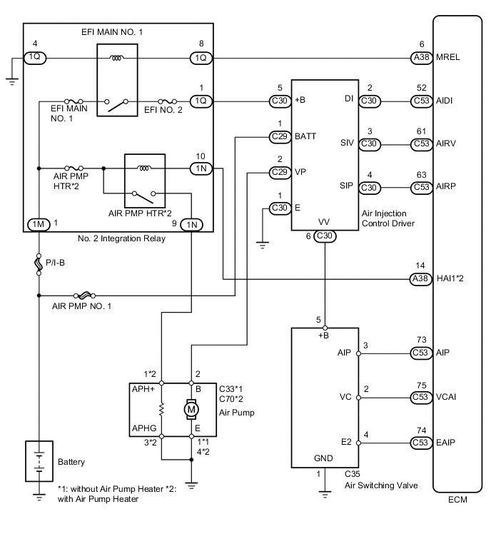
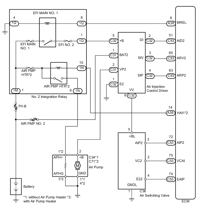
WIRING DIAGRAM
- for LHD [Bank 1]:
- for LHD [Bank 2]:
- for RHD [Bank 1]:
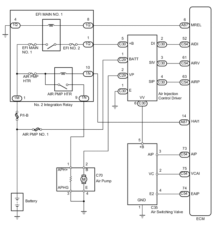
- for RHD [Bank 2]:

CAUTION / NOTICE / HINT
Tech Tips
-
By using the intelligent tester to perform the Secondary Air Injection Check operation in the Utility, the air-fuel ratio and the pressure in the secondary air injection system passage can be checked while the secondary air injection system is operating. This helps technicians to troubleshoot the system when it malfunctions.
-
Read freeze frame data using the intelligent tester. Freeze frame data records the engine condition when malfunctions are detected. When troubleshooting, freeze frame data can help determine if the vehicle was moving or stationary, if the engine was warmed up or not, if the air-fuel ratio was lean or rich, and other data from the time the malfunction occurred.
PROCEDURE
-
INSPECT AIR SWITCHING VALVE ASSEMBLY
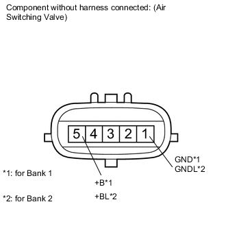
-
Disconnect the air switching valve (ASV) connector.
-
Measure the resistance according to the value(s) in the table below.
Standard Resistance Tester Connection Condition Specified Condition C35-5 (+B) - C35-1 (GND) 20°C (68°F) 4.5 to 5.5 Ω C36-5 (+BL) - C36-1 (GNDL) 20°C (68°F) 4.5 to 5.5 Ω
NG 
REPLACE AIR SWITCHING VALVE ASSEMBLY Click here
OK 
-
-
CHECK HARNESS AND CONNECTOR (AIR SWITCHING VALVE - BODY GROUND)
-
Disconnect the ASV connector.
-
Measure the resistance according to the value(s) in the table below.
Standard Resistance Tester Connection Condition Specified Condition C35-1 (GND) - Body ground Always Below 1 Ω C36-1 (GNDL) - Body ground Always Below 1 Ω
NG
REPAIR OR REPLACE HARNESS OR CONNECTOR
OK
-
-
CHECK HARNESS AND CONNECTOR (AIR SWITCHING VALVE - AIR INJECTION CONTROL DRIVER)
-
Disconnect the ASV connector.
-
Disconnect the AID connector.
-
Measure the resistance according to the value(s) in the table below.
Standard Resistance Tester Connection Condition Specified Condition C35-5 (+B) - C30-6 (VV) Always Below 1 Ω C36-5 (+BL) - C32-6 (VV2) Always Below 1 Ω C35-5 (+B) or C30-6 (VV) - Body ground Always 10 kΩ or higher C36-5 (+BL) or C32-6 (VV2) - Body ground Always 10 kΩ or higher
OK
REPLACE AIR INJECTION CONTROL DRIVER Click here
NG
REPAIR OR REPLACE HARNESS OR CONNECTOR
-