SEAT HEATER SYSTEM TERMINALS OF ECU
-
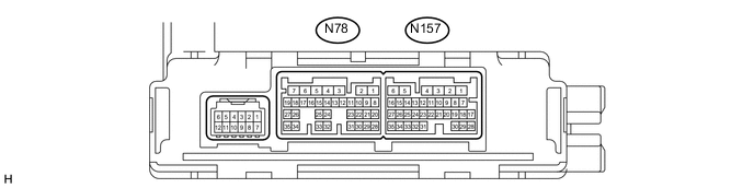
CHECK AIR CONDITIONING AMPLIFIER ASSEMBLY
-
Disconnect the N78 air conditioning amplifier assembly connector.
-
Measure the voltage and resistance according to the value(s) in the table below.
Terminal No. (Symbol) Wiring Color Terminal Description Condition Specified Condition N78-6 (+B1) - Body ground W - Body ground Power source (Back-up) Always 11 to 14 V N78-5 (IG+) - Body ground L - Body ground Power source (IG) Power switch on (IG) 11 to 14 V N78-1 (GND) - Body ground W-B - Body ground Ground Always Below 1 Ω If the result is not as specified, there may be a malfunction on the wire harness side.
-
Reconnect the N78 air conditioning amplifier assembly connector.
-
Measure the resistance and waveform according to the value(s) in the table below.
Terminal No. (Symbol) Wiring Color Terminal Description Condition Specified Condition N157-34 (SG-3) - Body ground GR - Body ground Ground Always Below 1 Ω N157-35 (SG-4) - Body ground B - Body ground Ground Always Below 1 Ω N78-20 (LIN1) - N78-1 (GND) R - W-B LIN communication signal Power switch on (IG) Pulse generation N78-21 (RLIN) - N78-1 (GND)* P - W-B LIN communication signal Power switch on (IG) Pulse generation
-
*: w/ Rear Seat Heater
-
-
-
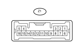
CHECK REAR CONTROL SWITCH (w/ Rear Seat Heater)
-
Disconnect the Z1 rear control switch connector.
-
Measure the voltage and resistance according to the value(s) in the table below.
Terminal No. (Symbol) Wiring Color Terminal Description Condition Specified Condition Z1-1 (+B) - Body ground R - Body ground Power source (Back-up) Always 11 to 14 V Z1-7 (IG+) - Body ground L - Body ground Power source (IG) Power switch on (IG) 11 to 14 V Z1-5 (E) - Body ground W-B - Body ground Ground Always Below 1 Ω If the result is not as specified, there may be a malfunction on the wire harness side.
-
Reconnect the Z1 rear control switch connector.
-
Measure the waveform according to the value(s) in the table below.
Terminal No. (Symbol) Wiring Color Terminal Description Condition Specified Condition Z1-9 (RLIN) - Z1-5 (E) P - W-B LIN communication signal Power switch on (IG) Pulse generation
-
-
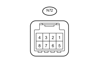
CHECK REFRESHING SEAT SWITCH
-
Disconnect the N72 refreshing seat switch connector.
-
Measure the voltage and resistance according to the value(s) in the table below.
Terminal No. (Symbol) Wiring Color Terminal Description Condition Specified Condition N72-1 (IG) - Body ground LG - Body ground Power source (IG) Power switch on (IG) 11 to 14 V N72-4 (E) - Body ground W-B - Body ground Ground Always Below 1 Ω If the result is not as specified, there may be a malfunction on the wire harness side.
-
Reconnect the N72 refreshing seat switch connector.
-
Measure the waveform according to the value(s) in the table below.
Terminal No. (Symbol) Wiring Color Terminal Description Condition Specified Condition N72-7 (SW) - N72-4 (E) R - W-B LIN communication signal Power switch on (IG) Pulse generation
-