PRE-CRASH SAFETY SYSTEM ECU Power Source Circuit
DESCRIPTION
This circuit supplies power to the driving support ECU assembly when the power switch is on (IG).
WIRING DIAGRAM
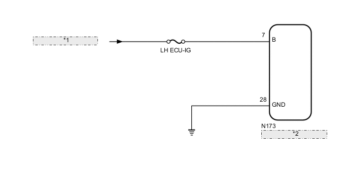
| *1 | from LH-IG1 RLY1 Relay |
| *2 | Driving Support ECU Assembly |
CAUTION / NOTICE / HINT
Note
Inspect the fuses for circuits related to this system before performing the following inspection procedure.
PROCEDURE
-
CHECK HARNESS OR CONNECTOR (DRIVING SUPPORT ECU ASSEMBLY - BATTERY AND BODY GROUND)
-
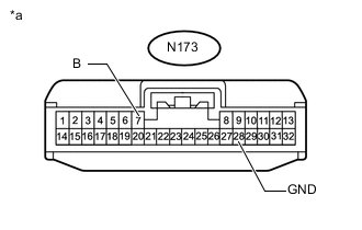
Text in Illustration *a Front view of wire harness connector
(to Driving Support ECU Assembly)
Disconnect the driving support ECU assembly connector.
-
Measure the voltage according to the value(s) in the table below.
Standard Voltage Tester Connection Switch Condition Specified Condition N173-7 (B) - Body ground Power switch on (IG) 11 to 14 V Power switch off Below 1 V -
Measure the resistance according to the value(s) in the table below.
Standard Resistance Tester Connection Condition Specified Condition N173-28 (GND) - Body ground Always Below 1 Ω
OK 
PROCEED TO NEXT SUSPECTED AREA SHOWN IN PROBLEM SYMPTOMS TABLE Click here
NG
REPAIR OR REPLACE HARNESS OR CONNECTOR
-