HEADUP DISPLAY SYSTEM Main Switch Circuit
DESCRIPTION
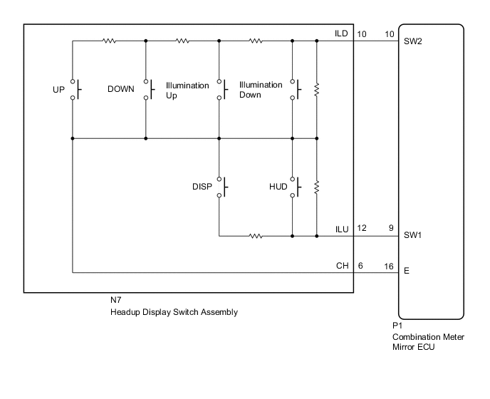
The combination meter mirror ECU is connected to the combination switch assembly (headup display switch) via a direct line. As a result, the combination meter mirror ECU can be turned on and off by operation of the combination switch assembly (headup display switch).
WIRING DIAGRAM
PROCEDURE
-
READ VALUE USING GTS (MAIN SW)
-
Using the GTS, read the Data List.
Headup Display Tester Display Test Part Control Range Diagnostic Note Main Switch Headup display main switch / ON or OFF ON: Switch pressed
OFF: Switch released
- Brightness Up Switch Brightness up switch / ON or OFF ON: Switch pressed
OFF: Switch released
- Brightness Down Switch Brightness down switch / ON or OFF ON: Switch pressed
OFF: Switch released
- Projection Position Up Switch Projection position up switch / ON or OFF ON: Switch pressed
OFF: Switch released
- Projection Position Down Switch Projection position up switch / ON or OFF ON: Switch pressed
OFF: Switch released
- Display Change Switch Display change switch / ON or OFF ON: Switch pressed
OFF: Switch released
- OK Headup display switch assembly condition displayed on the GTS changes with the actual switch operation.
NG 
REPLACE COMBINATION METER MIRROR ECU Click here
OK 
-
-
INSPECT HEADUP DISPLAY SWITCH ASSEMBLY
-
Remove the headup display switch assembly Click here.
-
Inspect the headup display switch assembly Click here.
NG
REPLACE HEADUP DISPLAY SWITCH ASSEMBLY Click here
OK
-
-
CHECK HARNESS AND CONNECTOR (METER MIRROR ECU - HEADUP DISPLAYSWITCH ASSEMBLY)
-
Disconnect the P1 combination meter mirror ECU connector.
-
Disconnect the N7 headup display switch assembly connector.
-
Measure the resistance according to the value(s) in the table below.
Standard Resistance Tester Connection Condition Specified Condition P1-9 (SW1) - N7-12 (ILU) Always Below 1 Ω P1-10 (SW2) - N7-10 (ILD) P1-16 (E) - N7-6 (CH) P1-9 (SW1) or N7-12 (ILU) - Body ground Always 10 kΩ or higher P1-10 (SW2) or N7-10 (ILD) - Body ground P1-16 (E) or N7-6 (CH) - Body ground
OK
REPLACE COMBINATION METER MIRROR ECU Click here
NG
REPAIR OR REPLACE HARNESS OR CONNECTOR
-