METER / GAUGE SYSTEM Speedometer Malfunction
DESCRIPTION
The combination meter receives vehicle speed signals from the skid control ECU assembly via the CAN communication line. The wheel speed sensors output voltages that vary according to the vehicle speed. The skid control ECU assembly supplies power to the wheel speed sensors. The skid control ECU assembly calculates the vehicle speed based on the pulses of the voltage.
WIRING DIAGRAM
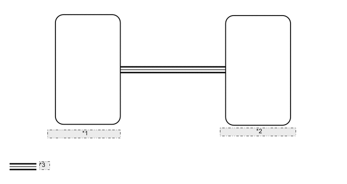
| *1 | Skid Control ECU Assembly |
| *2 | Combination Meter Assembly |
| *3 | CAN Communication Line |
CAUTION / NOTICE / HINT
Note
If the vehicle speed is outside the allowable range when tested, perform the on-vehicle inspection Click here.
PROCEDURE
-
CHECK CAN COMMUNICATION SYSTEM
-
Check if a CAN communication DTC is output.
-
for LHD (See page ).
-
for RHD Click here.
Result Result Proceed to CAN communication DTC is not output (except Sport Package) A CAN communication DTC is not output (for Sport Package) B CAN communication DTC is output (for LHD) C CAN communication DTC is output (for RHD) D
-
B 
READ VALUE USING GTS (VEHICLE SPEED METER) Click here
C 
GO TO CAN COMMUNICATION SYSTEM Click here
D
GO TO CAN COMMUNICATION SYSTEM Click here
A 
-
-
PERFORM ACTIVE TEST USING GTS (SPEED METER OPERATION)
-
Use the Active Test to check the operation of the speedometer Click here.
Combination Meter Tester Display Test Part Control Range Diagnostic Note Speed Meter Operation Speedometer OFF, 0, 40, 80, 120, 160, 200 or240 (mph)*1 - OFF, 0, 40, 80, 120, 160, 200 or 240 (km/h)*2
-
*1: for mph
-
*2: for km/h
OK Speedometer indication is normal. -
NG
REPLACE COMBINATION METER ASSEMBLY Click here
OK
-
-
READ VALUE USING GTS (VEHICLE SPEED METER)
-
Use the Data List to check if the speedometer is operating properly Click here.
Combination Meter Tester Display Measurement Item/Range Normal Condition Diagnostic Note Vehicle Speed Meter Vehicle speed / Min.: 0 mph (0 km/ h), Max.: 255 km/h (158 mph) Almost same as actual vehicle speed - OK Vehicle speed displayed on the GTS is almost the same as the actual vehicle speed measured using a speedometer tester (calibrated chassis dynamometer).
NG
REPLACE COMBINATION METER ASSEMBLY Click here
OK
-
-
READ VALUE USING GTS (FR/FL/RR/RL WHEEL SPEED)
-
Use the Data List to check the wheel speed Click here.
ABS/VSC/TRC Tester Display Measurement Item/Range Normal Condition Diagnostic Note FR Wheel Speed Vehicle speed / Min.: 0 mph (0 km/ h), Max.: 326 km/h (202 mph) Almost same as actual vehicle speed measured using speedometer tester - FL Wheel Speed Vehicle speed / Min.: 0 mph (0 km/ h), Max.: 326 km/h (202 mph) - RR Wheel Speed Vehicle speed / Min.: 0 mph (0 km/ h), Max.: 326 km/h (202 mph) - RL Wheel Speed Vehicle speed / Min.: 0 mph (0 km/ h), Max.: 326 km/h (202 mph) - OK Vehicle speed displayed on the GTS is almost the same as the actual vehicle speed measured using a speedometer tester (calibrated chassis dynamometer).
NG
GO TO ELECTRONICALLY CONTROLLED BRAKE SYSTEM Click here
OK
-
-
CHECK COMBINATION METER ASSEMBLY
-
Replace the combination meter assembly with a new or normally functioning one Click here.
-
Check the speedometer operation.
OK The operation of the speedometer returns to normal.
OK
END (COMBINATION METER ASSEMBLY WAS DEFECTIVE)
NG
REPLACE SKID CONTROL ECU ASSEMBLY Click here
-