ROOM LIGHT(for Front) INSPECTION
PROCEDURE
-
INSPECT MAP LIGHT ASSEMBLY
-
Inspect the resistance.
-
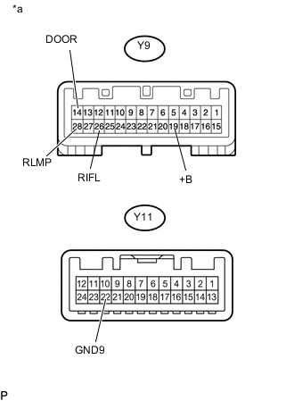
Text in Illustration *a Component without harness connected
(Map Light Assembly)
Measure the resistance according to the value(s) in the table below.
Standard Resistance Tester Connection Switch Condition Specified Condition Y9-14 (DOOR) - Y11-22 (GND9) Door switch on 10 kΩ or higher Door switch off Below 1 Ω Y9-19 (+B) - Y9-26 (RIFL) Always Below 1 Ω Y9-28 (RLMP) - Y11-22 (GND9) Always Below 1 Ω If the result is not as specified, replace the map light assembly.
-
-
Inspect the front map light.
-
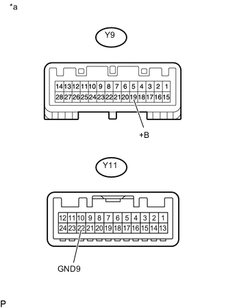
Text in Illustration *a Component without harness connected
(Map Light Assembly)
Apply battery voltage to the connector and check the light illumination condition.
OK Measurement Condition Condition Specified Condition Battery positive (+) → Y9-19 (+B1)
Battery negative (-) → Y11-22 (GND9)
Front map light switch LH on Front map light LH illuminates Front map light switch RH on Front map light RH illuminates Front dome light switch on Front dome light illuminates If the result is not as specified, replace the map light assembly.
-
-
Inspect the switch illumination.
-
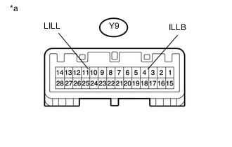
Text in Illustration *a Component without harness connected
(Map Light Assembly)
Apply battery voltage to the connector and check the light illumination condition.
OK Measurement Condition Specified Condition Battery positive (+) → Y9-4 (ILLB)
Battery negative (-) → Y9-11 (LILL)
Switch illumination illuminates If the result is not as specified, replace the map light assembly.
-
-