CAN COMMUNICATION SYSTEM(for LHD) DIAGNOSIS SYSTEM
-
CHECK FOR INSTALLED SYSTEMS (ECUS AND SENSORS) THAT USE CAN COMMUNICATION
-
The systems (ECUs and sensors) that use CAN communication vary depending on the vehicle and optional equipment. Check which systems (ECUs and sensors) are installed on the vehicle.
Tech Tips
The names of ECUs and sensors shown on the GTS display may differ from those shown in the DTC Table by ECU section that follows.
Bus ECU/Sensor Name GTS Display Applicability V Bus Central gateway ECU CAN Gateway All vehicles Bus 2 ECM ECM (Engine) All vehicles Central gateway ECU CAN Gateway All vehicles Parking brake ECU assembly Electric Parking Brake All vehicles Main body ECU (multiplex network body ECU) Main Body All vehicles Skid control ECU assembly Skid Control (ABS/VSC/TRAC) All vehicles Steering angle sensor Spiral cable (Steering Angle Sensor) All vehicles Airbag sensor assembly Airbag All vehicles Yaw rate sensor Yaw Rate Sensor All vehicles Certification ECU (smart key ECU assembly) Certification (Smart) All vehicles Air conditioning amplifier assembly Air Conditioning Amplifier All vehicles Power steering ECU assembly Power Steering (EPS) All vehicles Combination meter mirror ECU Head Up Display Vehicles with a headup display system Front steering control ECU Steering Control (VGRS) Vehicles with a variable gear ratio steering system Combination meter assembly Combination Meter All vehicles Power management control ECU Power Management1 All vehicles Bus 3 Central gateway ECU CAN Gateway All vehicles Multi-media module receiver assembly Display and Navigation (AVN1) All vehicles Telematics transceiver DCM Vehicles with a telematics transceiver Bus 4 Skid control ECU assembly Skid Control (ABS/VSC/TRAC) All vehicles Central gateway ECU CAN Gateway All vehicles Absorber control ECU Suspension Control (Air Suspension) Vehicles with an adaptive variable suspension system Power steering ECU assembly Power Steering (EPS) All vehicles Front steering control ECU Steering Control (VGRS) Vehicles with a variable gear ratio steering system Headlight ECU sub-assembly LH Headlight swivel (AFS) All vehicles Driving support ECU assembly Driving Support (Cruise Control-ACC) Vehicles with a pre-crash safety system Rear steering control ECU DRS Vehicles with a dynamic rear steering system Bus 5 Central gateway ECU CAN Gateway All vehicles Power management control ECU Power Management1 All vehicles Absorber control ECU Suspension Control (Air Suspension) Vehicles with an adaptive variable suspension system Headlight ECU sub-assembly LH Headlight swivel (AFS) All vehicles Driving support ECU assembly Driving Support (Cruise Control-ACC) Vehicles with a pre-crash safety system Forward recognition camera Front Camera Module Vehicles with a pre-crash safety system Millimeter wave radar sensor assembly Front Radar Vehicles with a pre-crash safety system Clearance warning ECU assembly Clearance warning (Clearance Sonar) Vehicles with a LEXUS parking assist-sensor system Blind spot monitor sensor RH Blind Spot Monitor Master Vehicles with a blind spot monitor system Sub Bus 1 Main body ECU (multiplex network body ECU) Main Body All vehicles Luggage closer motor assembly Back Door Vehicles with a power trunk lid system Multiplex network door ECU Back Door Vehicles without a power trunk lid system Position control ECU assembly LH D-Seat Vehicles an except standard seat type Power seat switch assembly D-Seat Vehicles with a standard seat type Position control ECU assembly RH P-Seat Vehicles with a luxury seat type Front multiplex network door ECU LH Front Door LH/L-Mirror (FL-Door2/L-Mirror) All vehicles Front multiplex network door ECU RH Front Door RH/R-Mirror (FR-Door2/R-Mirror) All vehicles Multiplex tilt and telescopic ECU Multiplex Tilt and Telescopic All vehicles Sub Bus 15 ECM ECM (Engine) All vehicles Power management control ECU Power Management1 All vehicles Skid control ECU assembly Skid Control (ABS/VSC/TRAC) All vehicles
-
-
CAN BUS CHECK
Tech Tips
The ECUs and sensors that are properly connected to the CAN communication system can be displayed using the GTS.
-
Using the GTS, select the CAN Bus Check screen.
Note
-
It may be possible to select buses that do not have ECUs or sensors from the bus selection pull-down menu. This is not a malfunction. (This occurs when optional devices are not on a sub bus that is monitored by a gateway function equipped ECU.)
-
It may be possible to select buses that do not have ECUs or sensors from the bus selection pull-down menu. This is not a malfunction. (This occurs when optional devices are not on a sub bus that is monitored by a gateway function equipped ECU.)
Tech Tips
Different connection statuses are indicated by the background color of ECUs and sensors that are displayed.
Explanation of CAN Bus Check Screen Bus Type Background Color Connection Status Bus White Communication has been normal. Yellow Communication stop occurred at least once since the start of the CAN bus check, but communication is currently occurring (unstable communication). Red Currently not communicating (either of the following):
-
Not communicating since the start of the CAN bus check
-
Communication occurred at least once since the start of the CAN bus check, but is currently not occurring.
Not displayed Either of the following:
-
The central gateway ECU (network gateway ECU) has an internal malfunction or cannot communicate with the GTS.*4
-
No ECUs or sensors are connected to the bus.*5
Sub bus with a gateway function equipped ECU that does not memorize connected ECUs or sensors*2 White Communication has been normal since the start of the CAN bus check. Yellow Communication stop occurred at least once since the start of the CAN bus check, but communication is currently occurring (unstable communication). Red Communication occurred at least once since the start of the CAN bus check, but is currently not occurring. Not displayed Communication stop has continued since the start of the CAN bus check.*1 Sub bus with a gateway function equipped ECU that memorizes connected ECUs and sensors*3 White Communication has been normal. Yellow Communication stop occurred at least once since the start of the CAN bus check, but communication is currently occurring (unstable communication). Red Currently not communicating (either of the following):
-
Not communicating since the start of the CAN bus check
-
Communication occurred at least once since the start of the CAN bus check, but is currently not occurring.
Not displayed Either of the following:
-
The gateway function equipped ECU cannot communicate with the central gateway ECU.*6
-
No ECUs or sensors are connected to the sub bus.*7
-
Gateway function equipped ECUs relay signals between ECUs and sensors connected to different buses.
-
*1: An ECU or sensor is installed to the vehicle but is not displayed on the "Communication Bus Check" screen.
-
*2: The gateway function equipped ECU does not memorize ECUs and sensors connected to its respective sub bus.
-
*3: The gateway function equipped ECU memorizes ECUs and sensors connected to its respective sub bus.
-
*4: When the central gateway ECU has an internal malfunction or cannot communicate with the GTS, the name of buses, sub buses, ECUs and sensors will not be displayed.
-
*5: When no ECUs or sensors are connected to a bus, the message "There is no system found on the communication Bus." will be displayed.
-
*6: When a gateway function equipped ECU cannot communicate with the central gateway ECU, the name of sub buses and ECUs or sensors connected to the sub bus will not be displayed.
-
*7: When no ECUs or sensors are connected to the sub bus, the message "There is no system found on the communication Bus." will be displayed.
-
If there is no communication between the GTS and the vehicle, or no ECUs or sensors are displayed as connected, check the central gateway ECU and V bus (the bus that connects the DLC3 to the central gateway ECU) for malfunctions.
-
-
Observe the connection response screen for approximately 2 minutes to check for a change in connection status of the connected ECUs and sensors.
Tech Tips
-
If an open occurs in one of the lines of a CAN branch (except DLC3), output from the other branch line (the line that is not open) will be unstable and it may interfere with the response (display) of other ECUs and sensors.
-
If the connection status changes during the inspection, repair the open in the branch line of the ECU or sensor that does not respond (is not detected) and then perform the CAN bus check again.
-
-
-
HOW TO INTERPRET CAN BUS CHECK SCREEN
-
When a communication stop is currently occurring, the probable malfunctioning part can be determined from the CAN bus check and by using the following methods.
Note
The following CAN bus wiring diagram is provided only as an example. This wiring diagram is different from the actual wiring diagram for this vehicle.
Tech Tips
-
When a communication stop is currently occurring, it is easier to determine the probable malfunctioning part from the CAN bus check rather than from communication DTCs.
-
Wait for approximately 2 minutes after turning the power switch on (IG) (or simulate the driving conditions that enable the malfunction to be reproduced) and select "CAN Bus Check". Then observe the communication status of each ECU on the screen.
-
-
If a communication error of only 1 ECU or sensor is indicated on the CAN Bus Check screen, a communication stop of the ECU or sensor is suspected.
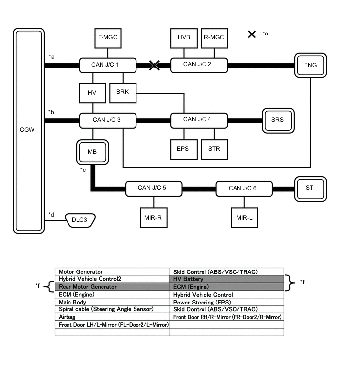
Open in both CAN branch lines of HV on the bus 4
*a Bus 2 *b Bus 4 *c Sub Bus *d V Bus *e Location of Malfunction *f Background color is red Tech Tips
When there are communication stops, ECUs that are present in the vehicle may not be displayed on the CAN Bus Check screen.
-
If communication errors for multiple ECUs or sensors are indicated on the CAN Bus Check screen, then a communication stop of the ECU or sensor that shows a more serious communication stop (an ECU or sensor whose background color is red) is suspected.
Example: Open in a CAN branch line for HV on the bus 4
*a Background color is red *b Background color intermittently becomes yellow or red *c Not displayed or background color is yellow or red - - Explanation of CAN Bus Check Screen Bus Type Background Color Connection Status Bus White Communication has been normal. Yellow Communication stop occurred at least once since the start of the CAN bus check, but communication is currently occurring (unstable communication). Red Currently not communicating (either of the following):
-
Not communicating since the start of the CAN bus check
-
Communication occurred at least once since the start of the CAN bus check, but is currently not occurring.
Not displayed Either of the following:
-
The central gateway ECU (network gateway ECU) has an internal malfunction or cannot communicate with the GTS.*4
-
No ECUs or sensors are connected to the bus.*5
Sub bus with a gateway function equipped ECU that does not memorize connected ECUs or sensors*2 White Communication has been normal since the start of the CAN bus check. Yellow Communication stop occurred at least once since the start of the CAN bus check, but communication is currently occurring (unstable communication). Red Communication occurred at least once since the start of the CAN bus check, but is currently not occurring. Not displayed Communication stop has continued since the start of the CAN bus check.*1 Sub bus with a gateway function equipped ECU that memorizes connected ECUs and sensors*3 White Communication has been normal. Yellow Communication stop occurred at least once since the start of the CAN bus check, but communication is currently occurring (unstable communication). Red Currently not communicating (either of the following):
-
Not communicating since the start of the CAN bus check
-
Communication occurred at least once since the start of the CAN bus check, but is currently not occurring.
Not displayed Either of the following:
-
The gateway function equipped ECU cannot communicate with the central gateway ECU.*6
-
No ECUs or sensors are connected to the sub bus.*7
-
Gateway function equipped ECUs relay signals between ECUs and sensors connected to different buses.
-
*1: An ECU or sensor is installed to the vehicle but is not displayed on the "Communication Bus Check" screen.
-
*2: The gateway function equipped ECU does not memorize ECUs and sensors connected to its respective sub bus.
-
*3: The gateway function equipped ECU memorizes ECUs and sensors connected to its respective sub bus.
-
*4: When the central gateway ECU (network gateway ECU) has an internal malfunction or cannot communicate with the GTS, the name of buses, sub buses, ECUs and sensors will not be displayed.
-
*5: When no ECUs or sensors are connected to a bus, the message "There is no system found on the communication Bus." will be displayed.
-
*6: When a gateway function equipped ECU cannot communicate with the central gateway ECU (network gateway ECU), the name of sub buses and ECUs or sensors connected to the sub bus will not be displayed.
-
*7: When no ECUs or sensors are connected to the sub bus, the message "There is no system found on the communication Bus." will be displayed.
-
The example of the CAN Bus Check screen in the illustration shows the result of electrical noise on the CAN bus which is caused by an open in a CAN branch line of HV is also unstable. In addition, in this example, MB is equipped with a gateway function. Therefore, communication is also unstable between the Sub bus ECUs of MB and the bus 4.
-
The example in the illustration shows that HV has a red background color on the CAN Bus Check screen. This indicates a more significant communication stop. In this case, a communication stop of HV is suspected.
-
-
If a communication error is indicated on both the bus 4 and Sub bus on the CAN Bus Check screen, suspect any communication stop displayed for the bus 4 first.
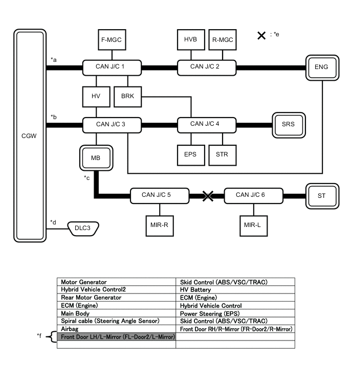
Example: Open in both CAN branch lines of MB on the bus 4
*a Background color is red *b Not displayed Tech Tips
-
In the CAN bus check, it is possible to confirm the communication status of ECUs connected to the bus after connecting the GTS to the DLC3. As for sub bus, it is possible to confirm which sub bus connected ECUs can communicate with a gateway function equipped ECU on the bus.
-
If a gateway function equipped ECU has a communication error, ECUs connected to the gateway function equipped ECU are also affected, and communication stops will be indicated.
-
The CAN Bus Check screen in the illustration shows that ECU G has a gateway function and a communication stop in ECU G is suspected.
-
-
If the CAN Bus Check screen indicates a communication stop only in the sub bus, a communication stop in the sub bus is suspected.
Example: Open in both CAN branch lines of MIR-R on the sub bus
*a Background color is red - - Tech Tips
-
A communication error in a sub bus does not affect the other buses.
-
When a gateway function equipped ECU has memorized the ECUs that are connected to the sub bus, if any of the ECUs connected to the gateway function equipped ECU has a communication error, the background color changes to yellow or red. (The displayed name will not disappear.)
-
-
If both of the bus 2 main bus lines are open, ECUs or sensors that are located farther away from the central gateway ECU than the open part will be displayed as a communication stop on the CAN Bus Check screen.
(In this case, HVB, R-MGC and ENG background color changes to red.)
*a Bus 2 *b Bus 4 *c Sub Bus *d V Bus *e Location of Malfunction *f Background color is red Tech Tips
If a communication error occurs in an ECU, it is not displayed on the CAN Bus Check screen even though the ECU is present.
-
If both of the sub bus main bus lines are open, ECUs that are located farther away from the gateway function equipped ECU than the open part will be displayed as a communication stop on the CAN Bus Check screen.
(In this case, MIR-L background color changes to red.)
*a Bus 2 *b Bus 4 *c Sub Bus *d V Bus *e Location of Malfunction *f Background color is red -
When any of the following malfunctions occur, CAN communication cannot be established and almost all ECUs and sensors on the bus show a communication error on the CAN Bus Check screen.
Details of Malfunction Short between CAN lines (CANH and CANL) Short between a CAN line (CANH or CANL) and +B Short between a CAN line (CANH or CANL) and ground Open in a CAN main bus line 
*a When any of the following malfunctions occur on the bus 4 *b When any of the following malfunctions occur on a sub bus *c Background color is red *d Not displayed Tech Tips
-
When a malfunction occurs in the bus, almost all ECUs and sensors on the bus and sub bus indicate a communication error (almost all ECUs are not displayed). As communication with the gateway function equipped ECU that is connected to the bus stops, communication from the ECUs connected to the sub bus that is monitored by the gateway function equipped ECU also stops (these ECUs are not displayed).
-
When a malfunction occurs in a sub bus, almost all ECUs connected to the sub bus indicate a communication error.
-
A communication error in a sub bus does not affect the other buses.
-
The malfunctioning part can be determined by checking for a short circuit between CAN bus lines or between a CAN bus line and ground or +B short using an electrical tester.
-
-
If a communication error of all ECUs and sensors is indicated on the CAN Bus Check screen, a communication stop of the V bus (DLC3 - central gateway ECU) is suspected.
Open in both CAN branch lines in the V bus
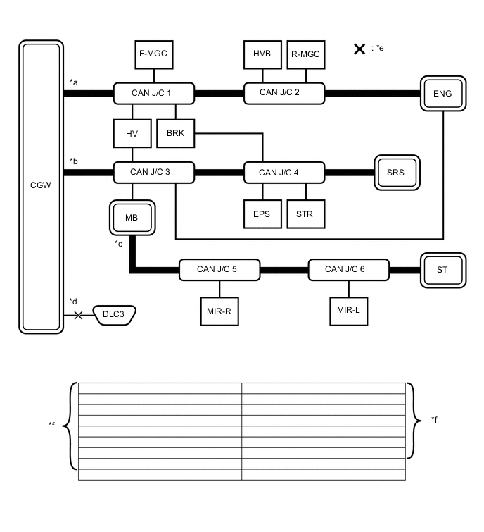
*a Bus 2 *b Bus 4 *c Sub Bus *d V Bus *e Location of Malfunction *f Not displayed Tech Tips
When there is no communication between the GTS and the vehicle, no ECUs or sensors will be displayed.
-
-
HOW TO INTERPRET COMMUNICATION DTCS (DTCS THAT START WITH U)
-
If a CAN communication error cannot be reproduced, determine the suspected malfunctioning part using the DTCs stored in ECUs that are connected to the CAN buses by following the procedure below.
Tech Tips
Communication DTCs (DTCs that start with U) indicate a communication error between the ECU that stores the DTC and the ECU that is indicated by the DTC.
-
If multiple ECUs store a communication DTC for a particular ECU, a communication stop of the ECU is suspected.
*a Items to be Checked - - Note
-
This DTC table is from another model, and is only used here to show an example of DTCs that are output when there is an open in a CAN branch line for the main body ECU. This table does not show DTCs applicable to this vehicle.
-
Even though a DTC title may indicate a communication error with a specific ECU, the ECU name used in the DTC name on the GTS may differ depending on the ECU that stores the DTC. (Regarding output DTCs, refer to the DTC chart for each ECU.)
Tech Tips
As multiple ECUs indicate a communication stop with the main body ECU, the possibility of a communication stop of the main body ECU is high.
-
-
If almost all of the communication DTCs of an ECU are stored, a communication stop of the ECU is suspected.
*a Items to be Checked - - Note
-
This DTC table is from another model, and is only used here to show an example of DTCs that are output when there is an open in a CAN branch line for the main body ECU. This table does not show DTCs applicable to this vehicle.
-
Even though a DTC title may indicate a communication error with a specific ECU, the ECU name used in the DTC name on the GTS may differ depending on the ECU that stores the DTC. (Regarding output DTCs, refer to DTC Table by ECU.)
Tech Tips
-
If almost all of the DTCs of the main body ECU are stored, the possibility of a communication stop of the main body ECU is high.
-
When a CAN communication error occurs, many DTCs are output. DTCs other than communication error DTCs (such as DTCs that start with C or B) and communication DTCs for the ABS system are important DTCs, however it may be easier to determine the malfunctioning part by examining the overall situation without considering these DTCs.
-
-
-
To help determine the part of the sub bus that has a communication error, prioritize the communication stop DTCs stored in the gateway function equipped ECU.
*a Items to be Checked *b ECM *c Gateway Function Equipped ECU *d Location of Malfunction *e Bus *f Sub Bus Note
This DTC table is from another model, and is only used here to show the ECUs connected to both a bus and a sub bus. It shows DTCs output when there is an open in the main bus lines for the ECM on the sub bus. This table does not show DTCs applicable to this vehicle.
Tech Tips
-
As gateway function equipped ECUs (sub bus monitor ECU) monitor signals from all ECUs that are connected to sub bus, gateway function equipped ECUs can detect ECUs with a communication stop more accurately.
-
When there is a communication stop for the gateway function equipped ECU (gateway), communication with ECUs connected to other buses such as the bus 2 stops. Therefore, communication DTCs for ECUs connected to other buses are also stored.
-
-
When any of the following malfunctions occurs, many DTCs are likely to be output from many ECUs. Because of this, it may be difficult to determine the probable malfunctioning part.
-
Short between CAN lines (CANH and CANL)
-
Short between a CAN line (CANH or CANL) and ground
-
Short between a CAN line (CANH or CANL) and +B
-
Open in a CAN branch line (CANH or CANL) of an ECU or sensor
-
Open in a CAN main bus line (CANH or CANL) between 2 ECUs that have a terminating resistor
-
-
-
DTC TABLE BY ECU
Tech Tips
-
In the CAN communication system, the CAN communication DTCs of each ECU can be displayed using the GTS.
-
If CAN communication system DTCs are output, trouble cannot be determined only by the DTCs. Perform troubleshooting according to How to Proceed with Troubleshooting Click here.
-
If system function temporarily returns to normal, DTCs may not be output again even though the following DTC check procedures are used.
-
Power Management Control ECU
Tech Tips
This ECU uses the CAN communication system for DTC communication.
-
GTS Display "Hybrid Control"
DTC Detection Item DTC Detection Condition DTC Detection Precondition DTC Check Procedure Warning Indication in Meter DTC Storage Method U0100-530 Lost Communication with ECM/PCM "A" The power management control ECU is unable to receive certain data from the ECM for approximately 1 second or more. Both conditions are met:
-
Approximately 1 second or more elapse after turning the power switch on (IG).
-
The power management control ECU power supply is 9.5 V or higher.
Turn the power switch on (IG) and wait at least approximately 2 seconds.
-
MIL indicator light illuminates.
-
Master warning light illuminates.
The DTC remains stored until it is cleared using the GTS. U0110-159*1 Lost Communication with Drive Motor Control Module "A" The response sent to the power management control ECU from the MG ECU is invalid for approximately 1 second or more. Both conditions are met:
-
Approximately 1 second or more elapse after turning the power switch on (IG).
-
The power management control ECU power supply is 9.5 V or higher.
Turn the power switch on (IG) and wait at least approximately 2 seconds. Master warning light illuminates. The DTC remains stored until it is cleared using the GTS. U0110-160*1 U0110-656*1 U0110-657*1 U0122-732*2 Lost Communication with Vehicle Dynamics Control Module The power management control ECU is unable to receive certain data from the skid control ECU assembly for approximately 3 seconds or more. Both conditions are met:
-
Approximately 3 seconds or more elapse after turning the power switch on (IG).
-
Cruise control switch on
-
The power management control ECU power supply is 9.5 V or higher.
After turning the power switch on (IG), turn the cruise control switch on and wait for at least approximately 6 seconds. Displays messages on the multi-information display. The DTC remains stored until it is cleared using the GTS. U0129-527 Lost Communication with Brake System Control Module The response sent to the power management control ECU from the skid control ECU assembly is invalid for approximately 3 seconds or more. Both conditions are met:
-
Approximately 3 seconds or more elapse after turning the power switch on (IG).
-
The power management control ECU power supply is 9.5 V or higher.
Turn the power switch on (IG) and wait at least approximately 6 seconds. Master warning light illuminates. The DTC remains stored until it is cleared using the GTS. U0129-528 U0140-146 Communication Error from Body ECU to HV ECU The response sent to the power management control ECU from the main body ECU (multiplex network body ECU) is invalid for approximately 4 seconds or more. Both conditions are met:
-
Approximately 1 second or more elapse after turning the power switch on (IG).
-
The power management control ECU power supply is 9.5 V or higher.
Turn the power switch on (IG) and wait at least approximately 5 seconds. Master warning light illuminates. The DTC remains stored until it is cleared using the GTS. U0151-763 Communication Error from Airbag ECU to HV ECU The response sent to the power management control ECU from the center airbag sensor assembly is invalid for approximately 11 seconds or more. Both conditions are met:
-
Approximately 1 second or more elapse after turning the power switch on (IG).
-
The power management control ECU power supply is 9.5 V or higher.
Turn the power switch on (IG) and wait at least approximately 12 seconds. Master warning light illuminates. The DTC remains stored until it is cleared using the GTS. U0164-827 Communication Error from A/C ECU to HV ECU The response sent to the power management control ECU from the air conditioning amplifier assembly is invalid for approximately 11 seconds or more. Both conditions are met:
-
Approximately 1 second or more elapse after turning the power switch on (IG).
-
The power management control ECU power supply is 9.5 V or higher.
Turn the power switch on (IG) and wait at least approximately 12 seconds. Master warning light illuminates. The DTC remains stored until it is cleared using the GTS. U029A-123*1 Lost Communication with Hybrid Battery Pack Sensor Module The response sent to the power management control ECU from the battery smart unit is invalid for approximately 1 second or more. Both conditions are met:
-
Approximately 1 second or more elapse after turning the power switch on (IG).
-
The power management control ECU power supply is 9.5 V or higher.
Turn the power switch on (IG) and wait at least approximately 2 seconds.
-
Master warning light illuminates.
-
MIL illuminates.
The DTC remains stored until it is cleared using the GTS. U0424-537*3 Invalid Data Received From HV AC Control Module The power management control ECU receives an abnormal operation value command from the air conditioning amplifier assembly for approximately 3 seconds or more. Both conditions are met:
-
Approximately 1 second or more elapse after turning the power switch on (IG).
-
The power management control ECU power supply is 9.5 V or higher.
Turn the power switch on (IG) and wait at least approximately 4 seconds. - The DTC remains stored until it is cleared using the GTS. U1107-436 Lost Communication with Power Management Module The response sent to the power management control ECU (HV CPU) from the power management control ECU (power management CPU) is invalid for approximately 4 seconds or more. Both conditions are met:
-
Approximately 1 second or more elapse after turning the power switch on (IG).
-
The power management control ECU power supply is 9.5 V or higher.
Turn the power switch on (IG) and wait at least approximately 5 seconds. Master warning light illuminates. The DTC remains stored until it is cleared using the GTS.
-
The power management control ECU stores DTCs for the dynamic radar cruise control system.
-
*1: Refer to the Hybrid Vehicle System.
-
for 2GR-FXE: Click here
-
for 2AR-FSE: Click here
-
*2: Cruise control system DTC.
-
*3: Even though a communication error is indicated on the GTS, the power management control ECU stores this DTC when it detects an internal malfunction in the air conditioning amplifier assembly.
-
for 2GR-FXE: Click here
-
for 2AR-FSE: Click here
-
-
GTS Display "Power Source Control"
DTC Detection Item DTC Detection Condition DTC Detection Precondition DTC Check Procedure Warning Indication in Meter DTC Storage Method U0140 Lost Communication with Body Control Module The response sent to the power management control ECU from the main body ECU (multiplex network body ECU) is invalid for approximately 4 seconds or more. Both conditions are met:
-
Approximately 10 seconds or more elapse after turning the power switch on (IG).
-
The power management control ECU power supply is 10 V or higher.
Turn the power switch on (IG) and wait at least approximately 20 seconds. - The DTC remains stored until it is cleared using the GTS. U0155 Lost Communication with Instrument Panel Cluster (IPC) Control Module The response sent to the power management control ECU from the combination meter assembly is invalid for approximately 4 seconds or more. Both conditions are met:
-
Approximately 10 seconds or more elapse after turning the power switch on (IG).
-
The power management control ECU power supply is 10 V or higher.
Turn the power switch on (IG) and wait at least approximately 20 seconds. - The DTC remains stored until it is cleared using the GTS. U0293* HV ECU Communication The response sent to the power management control ECU (power management CPU) from the power management control ECU (HV CPU) is invalid for approximately 4 seconds or more. Both conditions are met:
-
Approximately 10 seconds or more elapse after turning the power switch on (IG).
-
The power management control ECU power supply is 10 V or higher.
Turn the power switch on (IG) and wait at least approximately 14 seconds. - The DTC remains stored until it is cleared using the GTS.
-
*: If U0293 is output alone, CAN communication is normal.
-
-
-
ECM
Tech Tips
This ECU uses the CAN communication system for DTC communication.
-
GTS Display "Engine"
DTC Detection Item DTC Detection Condition DTC Detection Precondition DTC Check Procedure Warning Indication in Meter DTC Storage Method U0293 Lost Communication with Hybrid Vehicle Control System The ECM is unable to receive certain data from the power management control ECU for approximately 1 second or more. Both conditions are met:
-
Approximately 1 second or more elapse after turning the power switch on (IG).
-
The ECM power supply is 10.5 V or higher.
Turn the power switch on (IG) and wait at least approximately 2 seconds. MIL indicator light illuminates. The DTC remains stored until it is cleared using the GTS. -
-
GTS Display "Radar Cruise1"
DTC Detection Item DTC Detection Condition DTC Detection Precondition DTC Check Procedure Warning Indication in Meter DTC Storage Method U0100 Lost Communication with ECM / PCM "A" The ECM is unable to receive certain data from the skid control ECU assembly for approximately 1 second or more. Both conditions are met:
-
The power switch is on (IG).
-
The radar cruise control system (vehicle control mode) is operating.
Allow the radar cruise control system (vehicle control mode) to operate for approximately 1 second or more. Displays messages on the multi-information display. The DTC remains stored until it is cleared using the GTS. U0122 Lost Communication with Vehicle Dynamics Control Module When the vehicle speed is 50 km/h (31 mph) or more and is being controlled by the cruise control system in vehicle-to-vehicle distance control mode, the ECM does not receive data from the skid control ECU assembly for approximately 3 seconds or more. Both conditions are met:
-
The power switch is on (IG).
-
The radar cruise control system (vehicle control mode) is operating.
Allow the radar cruise control system (vehicle control mode) to operate for approximately 3 seconds or more Displays messages on the multi-information display. The DTC remains stored until it is cleared using the GTS. U1104 Lost Communication with Distance Control Module The driving support ECU assembly data sent to the ECM, master cylinder solenoid (skid control ECU) or millimeter wave radar sensor assembly is lost for approximately 1 second or more. Both conditions are met:
-
The power switch is on (IG).
-
The radar cruise control system (vehicle control mode) is operating.
Allow the radar cruise control system (vehicle control mode) to operate for approximately 1 second or more. Displays messages on the multi-information display. The DTC remains stored until it is cleared using the GTS. -
-
GTS Display "Cruise Control"
DTC Detection Item DTC Detection Condition DTC Detection Precondition DTC Check Procedure Warning Indication in Meter DTC Storage Method U0122 Lost Communication with Vehicle Dynamics Control Module The ECM is unable to receive certain data from the skid control ECU assembly for approximately 3 seconds or more. All of the following conditions are met:
-
Approximately 1 second or more elapse after turning the power switch on (IG).
-
The cruise control switch is on.
-
The ECM power supply is 10.5 V or higher.
Turn the power switch on (IG) and wait at least approximately 4 seconds. - The DTC remains stored until it is cleared using the GTS. -
-
-
Skid Control ECU Assembly / GTS Display "ABS/VSC/TRC"
Tech Tips
This ECU uses the CAN communication system for DTC communication.
DTC Detection Item DTC Detection Condition DTC Detection Precondition DTC Check Procedure Warning Indication in Meter DTC Storage Method U0073 Control Module Communication Bus OFF Either condition is met:
-
The response sent to the skid control ECU from the steering angle sensor is invalid for approximately 1 second or more.
-
The response sent to the skid control ECU from the yaw rate sensor is invalid for approximately 1 second or more.
-
The response sent to the skid control ECU from the front steering control ECU is invalid for approximately 1 second or more.
-
The response sent to the skid control ECU from the rear steering control ECU is invalid for approximately 1 second or more.
-
The following condition occurs 10 times consecutively within approximately 60 seconds:
-
The response sent to the skid control ECU from the yaw rate sensor is invalid at least once within 5 seconds.
-
The response sent to the skid control ECU from the steering angle sensor is invalid at least once within 5 seconds.
-
The response sent to the skid control ECU from the front steering control ECU is invalid at least once within 5 seconds.
-
The response sent to the skid control ECU from the rear steering control ECU is invalid at least once within 5 seconds.
-
The skid control ECU cannot send or receive data (the bus is off) 10 times consecutively.
Both conditions are met:
-
Approximately 1 second or more elapses after turning the power switch on (IG).
-
The skid control ECU assembly power supply voltage is between 10 and 17.4 V.
Turn the power switch on (IG) and wait at least approximately 60 seconds.
-
ABS indicator light illuminates.
-
Brake indicator light illuminates.
-
SLIP indicator light illuminates.
The DTC remains stored until it is cleared using the GTS. U0120 Lost Communication With Starter / Generator Control Module The skid control ECU assembly is unable to receive certain data from the certification ECU (smart key ECU assembly) for approximately 3 seconds or more. All conditions are met:
-
Approximately 1 second or more elapses after turning the power switch on (IG).
-
The skid control ECU assembly power supply voltage is between 10 and 17.4 V.
Turn the power switch on (IG) and wait at least approximately 4 seconds. ECB warning light illuminates. The DTC remains stored until it is cleared using the GTS. U0123 Lost Communication with Yaw Rate Sensor Module Either condition is met:
-
The skid control ECU assembly is unable to receive certain data from the yaw rate sensor for approximately 1 second or more.
-
The following condition occurs 10 times or more consecutively within approximately 60 seconds:
-
The skid control ECU assembly is unable to receive certain data from the yaw rate sensor at least once within approximately 5 seconds.
Both conditions are met:
-
Approximately 1 second or more elapses after turning the power switch on (IG).
-
The skid control ECU assembly power supply voltage is between 10 and 17.4 V.
Turn the power switch on (IG) and wait at least approximately 60 seconds.
-
ABS indicator light illuminates.
-
SLIP indicator light illuminates.
-
Brake hold standby indicator light blinks.
-
ECB warning light illuminates.
The DTC remains stored until it is cleared using the GTS. U0124 Lost Communication with Lateral Acceleration Sensor Module Either condition is met:
-
The skid control ECU assembly is unable to receive certain data from the yaw rate sensor for approximately 1 second or more.
-
The following condition occurs 10 times or more consecutively within approximately 60 seconds:
-
The skid control ECU assembly is unable to receive certain data from the yaw rate sensor at least once within approximately 5 seconds.
Both conditions are met:
-
Approximately 1 second or more elapses after turning the power switch on (IG).
-
The skid control ECU assembly power supply voltage is between 10 and 17.4 V.
Turn the power switch on (IG) and wait at least approximately 60 seconds.
-
ABS indicator light illuminates.
-
SLIP indicator light illuminates.
-
Brake hold standby indicator light blinks.
-
ECB warning light illuminates.
The DTC remains stored until it is cleared using the GTS. U0126 Lost Communication with Steering Angle Sensor Module Either condition is met:
-
The skid control ECU assembly is unable to receive certain data from the steering angle sensor for approximately 1 second or more.
-
The following condition occurs 10 times or more consecutively within approximately 60 seconds:
-
The skid control ECU assembly is unable to receive certain data from the steering angle sensor at least once within approximately 5 seconds.
Both conditions are met:
-
Approximately 1 second or more elapses after turning the power switch on (IG).
-
The skid control ECU assembly power supply voltage is between 10 and 17.4 V.
Turn the power switch on (IG) and wait at least approximately 60 seconds. SLIP indicator light illuminates. The DTC remains stored until it is cleared using the GTS. U0128 Lost Communication With EPB Module The skid control ECU assembly is unable to receive certain data from the parking brake ECU assembly for approximately 1 second or more. Both conditions are met:
-
Approximately 1 second or more elapses after turning the power switch on (IG).
-
The skid control ECU assembly power supply voltage is between 10 and 17.4 V.
Turn the power switch on (IG) and wait at least approximately 2 seconds. Brake hold standby indicator light blinks. The DTC remains stored until it is cleared using the GTS. U0130 Lost Communication with Steering Effort Control Module Either condition is met:
-
The skid control ECU assembly is unable to receive certain data from the front steering control ECU for approximately 1 second or more.
-
The following condition occurs 10 times or more consecutively within approximately 60 seconds:
-
The skid control ECU assembly is unable to receive certain data from the front steering control ECU at least once within approximately 5 seconds.
Both conditions are met:
-
Approximately 1 second or more elapses after turning the power switch on (IG).
-
The skid control ECU assembly power supply voltage is between 10 and 17.4 V.
Turn the power switch on (IG) and wait at least approximately 60 seconds. SLIP indicator light illuminates. The DTC remains stored until it is cleared using the GTS. U0134 Lost Communication with DRS Module Either condition is met:
-
The skid control ECU assembly is unable to receive certain data from the rear steering control ECU for approximately 1 second or more.
-
The following condition occurs 10 times or more consecutively within approximately 60 seconds:
-
The skid control ECU assembly is unable to receive certain data from the rear steering control ECU at least once within approximately 5 seconds.
Both conditions are met:
-
Approximately 1 second or more elapses after turning the power switch on (IG).
-
The skid control ECU assembly power supply voltage is between 10 and 17.4 V.
Turn the power switch on (IG) and wait at least approximately 60 seconds. SLIP indicator light illuminates. The DTC remains stored until it is cleared using the GTS. U0293 Lost Communication with Hybrid Vehicle Control System Either condition is met:
-
The skid control ECU assembly is unable to receive certain data from the power management control ECU for approximately 2 seconds or more.
-
The following condition occurs 10 times or more consecutively within approximately 60 seconds:
-
The skid control ECU assembly is unable to receive certain data from the power management control ECU at least once within approximately 5 seconds.
Both conditions are met:
-
Approximately 1 second or more elapses after turning the power switch on (IG).
-
The skid control ECU assembly power supply voltage is between 10 and 17.4 V.
Turn the power switch on (IG) and wait at least approximately 60 seconds. SLIP indicator light illuminates. The DTC remains stored until it is cleared using the GTS. -
-
Combination Meter Assembly / GTS Display "Combination Meter"
Tech Tips
This ECU uses the CAN communication system for DTC communication.
DTC Detection Item DTC Detection Condition DTC Detection Precondition DTC Check Procedure Warning Indication in Meter DTC Storage Method U0100 Lost Communication with ECM/PCM "A" Either condition is met:
-
The combination meter assembly is unable to receive certain data from the ECM for approximately 2 seconds or more.
-
The combination meter assembly is unable to receive certain data from the power management control ECU for approximately 3 seconds or more.
Both conditions are met:
-
Approximately 10 seconds or more elapse after a power source mode change is detected (+B changes from off to on, ACC changes between on and off, or IG changes between on and off).
-
The voltage at the IG power supply terminal of the combination meter assembly is between 9.5 and 11.5 V.
Turn the power switch is on (IG) and wait at least approximately 13 seconds. - The DTC remains stored until it is cleared using the GTS. U0129 Lost Communication with Brake System Control Module Either condition is met:
-
The combination meter assembly is unable to receive certain data from the skid control ECU assembly for approximately 2 seconds or more.
-
The combination meter assembly is unable to receive certain data from the skid control ECU assembly for approximately 3 seconds or more.
Both conditions are met:
-
Approximately 10 seconds or more elapse after a power source mode change is detected (+B changes from off to on, ACC changes between on and off, or IG changes between on and off).
-
The voltage at the IG power supply terminal of the combination meter assembly is between 9.5 and 11.5 V.
Turn the power switch is on (IG) and wait at least approximately 13 seconds. - The DTC remains stored until it is cleared using the GTS. U0130 Lost Communication with VGRS The combination meter assembly is unable to receive certain data from the front steering control ECU for approximately 3 seconds or more. Both conditions are met:
-
Approximately 10 seconds or more elapse after a power source mode change is detected (+B changes from off to on, ACC changes between on and off, or IG changes between on and off).
-
The voltage at the IG power supply terminal of the combination meter assembly is between 9.5 and 11.5 V.
Turn the power switch is on (IG) and wait at least approximately 13 seconds. Displays messages on the multi-information display. The DTC remains stored until it is cleared using the GTS. U0131 Lost Communication with Power Steering Control Module The combination meter assembly is unable to receive certain data from the power steering ECU assembly for 3 seconds or more. Both conditions are met:
-
Approximately 10 seconds or more elapse after a power source mode change is detected (+B changes from off to on, ACC changes between on and off, or IG changes between on and off).
-
The voltage at the IG power supply terminal of the combination meter assembly is between 9.5 and 11.5 V.
Turn the power switch is on (IG) and wait at least approximately 13 seconds. The EPS warning light illuminates. The DTC remains stored until it is cleared using the GTS. U0134 Lost Communication with DRS Module The combination meter assembly is unable to receive certain data from the rear steering control ECU for 3 seconds or more. Both conditions are met:
-
Approximately 10 seconds or more elapse after a power source mode change is detected (+B changes from off to on, ACC changes between on and off, or IG changes between on and off).
-
The voltage at the IG power supply terminal of the combination meter assembly is between 9.5 and 11.5 V.
Turn the power switch is on (IG) and wait at least approximately 13 seconds. Displays messages on the multi-information display. The DTC remains stored until it is cleared using the GTS. U0142 Lost Communication with Body Control Module "B" Either condition is met:
-
The combination meter assembly is unable to receive certain data from the main body ECU (multiplex network body ECU) for approximately 3 seconds or more.
-
The combination meter assembly is unable to receive certain data from the main body ECU (multiplex network body ECU) for approximately 10 seconds or more.
Both conditions are met:
-
Approximately 10 seconds or more elapse after a power source mode change is detected (+B changes from off to on, ACC changes between on and off, or IG changes between on and off).
-
The voltage at the IG power supply terminal of the combination meter assembly is between 9.5 and 11.5 V.
Turn the power switch is on (IG) and wait at least approximately 20 seconds. - The DTC remains stored until it is cleared using the GTS. U0151 Lost Communication with Restraints Control Module The combination meter assembly is unable to receive certain data from the airbag sensor assembly for approximately 3 seconds or more. Both conditions are met:
-
Approximately 10 seconds or more elapse after a power source mode change is detected (+B changes from off to on, ACC changes between on and off, or IG changes between on and off).
-
The voltage at the IG power supply terminal of the combination meter assembly is between 9.5 and 11.5 V.
Turn the power switch is on (IG) and wait at least approximately 13 seconds. SRS warning light illuminated. The DTC remains stored until it is cleared using the GTS. U0163 Lost Communication With Navigation Control Module The combination meter assembly is unable to receive certain data from the center multi-media module receiver assembly for approximately 10 seconds or more. Both conditions are met:
-
Approximately 10 seconds or more elapse after a power source mode change is detected (+B changes from off to on, ACC changes between on and off, or IG changes between on and off).
-
The voltage at the IG power supply terminal of the combination meter assembly is between 9.5 and 11.5 V.
Turn the power switch is on (IG) and wait at least approximately 20 seconds. - The DTC remains stored until it is cleared using the GTS. U0182 Lost Communication with Lighting Control Module Front The combination meter assembly is unable to receive certain data from the headlight ECU sub-assembly LH for approximately 10 seconds or more. Both conditions are met:
-
Approximately 10 seconds or more elapse after a power source mode change is detected (+B changes from off to on, ACC changes between on and off, or IG changes between on and off).
-
The voltage at the IG power supply terminal of the combination meter assembly is between 9.5 and 11.5 V.
Turn the power switch is on (IG) and wait at least approximately 20 seconds. Displays messages on the multi-information display. The DTC remains stored until it is cleared using the GTS. U023A Lost Communication with Front Camera Module The combination meter assembly is unable to receive certain data from the center forward recognition camera for approximately 10 seconds or more. Both conditions are met:
-
Approximately 10 seconds or more elapse after a power source mode change is detected (+B changes from off to on, ACC changes between on and off, or IG changes between on and off).
-
The voltage at the IG power supply terminal of the combination meter assembly is between 9.5 and 11.5 V.
Turn the power switch is on (IG) and wait at least approximately 20 seconds. - The DTC remains stored until it is cleared using the GTS. U1104 Lost Communication with Driving Support ECU The combination meter assembly is unable to receive certain data from the center driving support ECU assembly for approximately 10 seconds or more. Both conditions are met:
-
Approximately 10 seconds or more elapse after a power source mode change is detected (+B changes from off to on, ACC changes between on and off, or IG changes between on and off).
-
The voltage at the IG power supply terminal of the combination meter assembly is between 9.5 and 11.5 V.
Turn the power switch is on (IG) and wait at least approximately 20 seconds. PCS warning light illuminated. The DTC remains stored until it is cleared using the GTS. -
-
Power Steering ECU Assembly / GTS Display "EMPS"
Tech Tips
This ECU uses the CAN communication system for DTC communication.
DTC Detection Item DTC Detection Condition DTC Detection Precondition DTC Check Procedure Warning Indication in Meter DTC Storage Method U0129 Lost Communication with Brake System Control Module The power steering ECU assembly is unable to receive certain data from the skid control ECU assembly for approximately 3 seconds or more. Both conditions are met:
-
Approximately 3 seconds or more elapse after turning the power switch on (IG).
-
The power steering ECU assembly power supply voltage is 9 V or higher.
Turn the power switch on (IG) and wait at least approximately 6 seconds. The EPS warning light illuminates. The DTC is stored only while the malfunction is present. U0130 Lost Communication with Steering Effort Control Module The power steering ECU assembly is unable to receive certain data from the front steering control ECU for approximately 2 seconds or more. Both conditions are met:
-
Approximately 3 seconds or more elapse after turning the power switch on (IG).
-
The power steering ECU assembly power supply voltage is 9 V or higher.
Turn the power switch on (IG) and wait at least approximately 5 seconds. - The DTC is stored only while the malfunction is present. U0132 Lost Communication with Ride Level Control Module The power steering ECU assembly is unable to receive certain data from the absorber control ECU for approximately 7 seconds or more. Both conditions are met:
-
Approximately 3 seconds or more elapse after turning the power switch on (IG).
-
The power steering ECU assembly power supply voltage is 9 V or higher.
Turn the power switch on (IG) and wait at least approximately 10 seconds. - The DTC is stored only while the malfunction is present. U0134 Lost Communication with DRS Module The power steering ECU assembly is unable to receive certain data from the rear steering control ECU for approximately 2 seconds or more. Both conditions are met:
-
Approximately 3 seconds or more elapse after turning the power switch on (IG).
-
The power steering ECU assembly power supply voltage is 9 V or higher.
Turn the power switch on (IG) and wait at least approximately 5 seconds. - The DTC is stored only while the malfunction is present. U0293 Lost Communication with Hybrid Control Module The power steering ECU assembly is unable to receive certain data from the power management control ECU for approximately 5 seconds or more. All conditions are met:
-
Approximately 3 seconds or more elapse after turning the power switch on (IG).
-
The vehicle speed is 20 km/h (12 mph) or more.
-
The power steering ECU assembly power supply voltage is 9 V or higher.
Drive the vehicle for approximately 300 seconds at a speed of 20 km/h (12 mph) or more. The EPS warning light illuminates. The DTC is stored only while the malfunction is present. U1104 Lost Communication with Driving Support ECU The power steering ECU assembly is unable to receive certain data from the forward recognition camera for approximately 2 seconds or more. Approximately 3 seconds or more elapse after turning the power switch on (IG). Turn the power switch on (IG) and wait at least approximately 5 seconds. - The DTC is stored only while the malfunction is present. -
-
Front Steering Control ECU (w/ Variable Gear Ratio Steering System) / GTS Display "VGRS"
Tech Tips
This ECU uses the CAN communication system for DTC communication.
DTC Detection Item DTC Detection Condition DTC Detection Precondition DTC Check Procedure Warning Indication in Meter DTC Storage Method U0101 Lost Communication with TCM The front steering control ECU is unable to receive certain data from the ECM for approximately 12 seconds or more. Both conditions are met:
-
Approximately 1 second or more elapses after turning the power switch on (IG).
-
The front steering control ECU power supply voltage is 10 to 16 V.
Turn the power switch on (IG) and wait at least approximately 13 seconds. - The DTC remains stored until it is cleared using the GTS. U0125 Lost Communication with Yaw Rate Sensor Module The front steering control ECU is unable to receive certain data from the yaw rate sensor for approximately 12 seconds or more. Both conditions are met:
-
Approximately 1 second or more elapses after turning the power switch on (IG).
-
The front steering control ECU power supply voltage is 10 to 16 V.
Turn the power switch on (IG) and wait at least approximately 13 seconds. - The DTC remains stored until it is cleared using the GTS. U0126 Lost Communication with Steering Angle Sensor Module The front steering control ECU is unable to receive certain data from the steering angle sensor for approximately 3 seconds or more. Both conditions are met:
-
Approximately 1 second or more elapses after turning the power switch on (IG).
-
The front steering control ECU power supply voltage is 10 to 16 V.
Turn the power switch on (IG) and wait at least approximately 4 seconds. - The DTC remains stored until it is cleared using the GTS. U0129 Lost Communication with Brake System Control Module Either condition is met:
-
The front steering control ECU is unable to receive certain data from the skid control ECU assembly for approximately 3 seconds or more.
-
The front steering control ECU is unable to receive certain data from the skid control ECU assembly for approximately 12 seconds or more.
Both conditions are met:
-
Approximately 2 second or more elapses after turning the power switch on (IG).
-
The front steering control ECU power supply voltage is 10 to 16 V.
Turn the power switch on (IG) and wait at least approximately 14 seconds. - The DTC remains stored until it is cleared using the GTS. U0131 Lost Communication with Power Steering Control Module The front steering control ECU is unable to receive certain data from the power steering ECU assembly for approximately 3 seconds or more. Both conditions are met:
-
Approximately 1 second or more elapses after turning the power switch on (IG).
-
The front steering control ECU power supply voltage is 10 to 16 V.
Turn the power switch on (IG) and wait at least approximately 4 seconds. - The DTC remains stored until it is cleared using the GTS. U0134 Lost Communication with DRS Module The front steering control ECU is unable to receive certain data from the rear steering control ECU for approximately 3 seconds or more. Both conditions are met:
-
Approximately 1 second or more elapses after turning the power switch on (IG).
-
The front steering control ECU power supply voltage is 10 to 16 V.
Turn the power switch on (IG) and wait at least approximately 4 seconds. - The DTC remains stored until it is cleared using the GTS. U0293 Lost Communication with Hybrid Vehicle Control System The front steering control ECU is unable to receive certain data from the power management control ECU for approximately 3 seconds or more. Both conditions are met:
-
Approximately 1 second or more elapses after turning the power switch on (IG).
-
The front steering control ECU power supply voltage is 10 to 16 V.
Turn the power switch on (IG) and wait at least approximately 4 seconds. - The DTC remains stored until it is cleared using the GTS. -
-
Rear Steering Control ECU (w/ Dynamic Rear Steering System) / GTS Display "DRS"
Tech Tips
This ECU uses the CAN communication system for DTC communication.
DTC Detection Item DTC Detection Condition DTC Detection Precondition DTC Check Procedure Warning Indication in Meter DTC Storage Method U0129 Lost Communication with Brake System Control Module The rear steering control ECU is unable to receive certain data from the skid control ECU assembly for approximately 3 seconds or more. Both conditions are met:
-
Approximately 2 seconds or more elapse after turning the power switch on (IG).
-
The rear steering control ECU power supply voltage is 10 V or less, or 16 V or higher.
Turn the power switch on (IG) and wait at least approximately 5 seconds. - The DTC remains stored until it is cleared using the GTS. U0130 Lost Communication with Steering Effort Control Module The rear steering control ECU is unable to receive certain data from the front steering control ECU for approximately 3 seconds or more. Both conditions are met:
-
Approximately 1 second or more elapses after turning the power switch on (IG).
-
The rear steering control ECU power supply voltage is 10 V or less, or 16 V or higher.
Turn the power switch on (IG) and wait at least approximately 4 seconds. - The DTC remains stored until it is cleared using the GTS. U0293 Lost Communication with Hybrid Vehicle Control System The rear steering control ECU is unable to receive certain data from the power management control ECU for approximately 3 seconds or more. Both conditions are met:
-
Approximately 1 second or more elapses after turning the power switch on (IG).
-
The rear steering control ECU power supply voltage is 10 V or less, or 16 V or higher.
Turn the power switch on (IG) and wait at least approximately 4 seconds. - The DTC remains stored until it is cleared using the GTS. -
-
Certification ECU (Smart Key ECU Assembly) / GTS Display "Entry&Start"
Tech Tips
This ECU uses the CAN communication system for DTC communication.
DTC Detection Item DTC Detection Condition DTC Detection Precondition DTC Check Procedure Warning Indication in Meter DTC Storage Method U0100 Lost Communication with ECM/PCM "A" The certification ECU (smart key ECU assembly) is unable to receive certain data from the ECM for approximately 10 seconds or more. Both conditions are met:
-
Approximately 10 seconds or more elapse after a power source mode change is detected (+B changes from off to on, on ACC changes between on and off, or IG changes between on and off).
-
The certification ECU (smart key ECU assembly) power supply voltage is 10 V or higher.
Wait approximately 20 seconds after turning the power switch on (ACC) or on (IG). - The DTC remains stored until it is cleared using the GTS. U0142 Lost Communication with Body Control Module "B" The certification ECU (smart key ECU assembly) is unable to receive certain data from the main body ECU (multiplex network body ECU) for approximately 10 seconds or more. Both conditions are met:
-
Approximately 10 seconds or more elapse after a power source mode change is detected (+B changes from off to on, ACC changes between on and off, or IG changes between on and off).
-
The certification ECU (smart key ECU assembly) power supply voltage is 10 V or higher.
Wait approximately 20 seconds after turning the power switch on (ACC) or on (IG). - The DTC remains stored until it is cleared using the GTS. U0155 Lost Communication with Instrument Panel Cluster (IPC) Control Module The certification ECU (smart key ECU assembly) is unable to receive certain data from the combination meter assembly for approximately 10 seconds or more. Both conditions are met:
-
Approximately 10 seconds or more elapse after a power source mode change is detected (+B changes from off to on, ACC changes between on and off, or IG changes between on and off).
-
The certification ECU (smart key ECU assembly) power supply voltage is 10 V or higher.
Wait approximately 20 seconds after turning the power switch on (ACC) or on (IG). - The DTC remains stored until it is cleared using the GTS. U0293 Lost Communication with Hybrid Vehicle Control System The certification ECU (smart key ECU assembly) is unable to receive certain data from the power management control ECU for approximately 10 seconds or more. Both conditions are met:
-
Approximately 10 seconds or more elapse after a power source mode change is detected (+B changes from off to on, ACC changes between on and off, or IG changes between on and off).
-
The certification ECU (smart key ECU assembly) power supply voltage is 10 V or higher.
Wait approximately 20 seconds after turning the power switch on (ACC) or on (IG). - The DTC remains stored until it is cleared using the GTS. -
-
Main Body ECU (Multiplex Network Body ECU) / GTS Display "Main Body"
Tech Tips
-
This ECU uses the CAN communication system for DTC communication.
-
"Gateway" stores DTCs when a communication error is detected in the sub bus 1.
DTC Detection Item DTC Detection Condition DTC Detection Precondition DTC Check Procedure Warning Indication in Meter DTC Storage Method U0100 Lost Communication with ECM/PCM "A" The main body ECU (multiplex network body ECU) is unable to receive certain data from the ECM for approximately 10 seconds or more. Both conditions are met:
-
Approximately 10 seconds or more elapse after a power source mode change is detected (+B changes from off to on, ACC changes between on and off, or IG changes between on and off).
-
The main body ECU (multiplex network body ECU) power supply voltage is 10 V or higher.
Turn the power switch on (IG) and wait at least approximately 20 seconds. - The DTC remains stored until it is cleared using the GTS. U0101 Lost Communication with TCM The main body ECU (multiplex network body ECU) is unable to receive certain data from the ECM for approximately 10 seconds or more. Both conditions are met:
-
Approximately 10 seconds or more elapse after a power source mode change is detected (+B changes from off to on, ACC changes between on and off, or IG changes between on and off).
-
The main body ECU (multiplex network body ECU) power supply voltage is 10 V or higher.
Turn the power switch on (IG) and wait at least approximately 20 seconds. - The DTC remains stored until it is cleared using the GTS. U0120 Lost Communication with Starter / Generator Control Module The main body ECU (multiplex network body ECU) is unable to receive certain data from the certification ECU (smart key ECU assembly) for approximately 10 seconds or more. Both conditions are met:
-
Approximately 10 seconds or more elapse after a power source mode change is detected (+B changes from off to on, ACC changes between on and off, or IG changes between on and off).
-
The main body ECU (multiplex network body ECU) power supply voltage is 10 V or higher.
Turn the power switch on (IG) and wait at least approximately 20 seconds. - The DTC remains stored until it is cleared using the GTS. U0151 Lost Communication with Restraints Control Module The main body ECU (multiplex network body ECU) is unable to receive certain data from the airbag sensor assembly for approximately 10 seconds or more. Both conditions are met:
-
Approximately 10 seconds or more elapse after a power source mode change is detected (+B changes from off to on, ACC changes between on and off, or IG changes between on and off).
-
The main body ECU (multiplex network body ECU) power supply voltage is 10 V or higher.
Turn the power switch on (IG) and wait at least approximately 20 seconds. - The DTC remains stored until it is cleared using the GTS. U0155 Lost Communication with Instrument Panel Cluster (IPC) Control Module The main body ECU (multiplex network body ECU) is unable to receive certain data from the combination meter assembly for approximately 10 seconds or more. Both conditions are met:
-
Approximately 10 seconds or more elapse after a power source mode change is detected (+B changes from off to on, ACC changes between on and off, or IG changes between on and off).
-
The main body ECU (multiplex network body ECU) power supply voltage is 10 V or higher.
Turn the power switch on (IG) and wait at least approximately 20 seconds. - The DTC remains stored until it is cleared using the GTS. U0164 Lost Communication with HVAC Control Module The main body ECU (multiplex network body ECU) is unable to receive certain data from the air conditioning amplifier assembly for approximately 10 seconds or more. Both conditions are met:
-
Approximately 10 seconds or more elapse after a power source mode change is detected (+B changes from off to on, ACC changes between on and off, or IG changes between on and off).
-
The main body ECU (multiplex network body ECU) power supply voltage is 10 V or higher.
Turn the power switch on (IG) and wait at least approximately 20 seconds. - The DTC remains stored until it is cleared using the GTS. U0182 Lost Communication with AFS The main body ECU (multiplex network body ECU) is unable to receive certain data from the headlight ECU sub-assembly LH for approximately 5 seconds or more. Both conditions are met:
-
Approximately 10 seconds or more elapse after a power source mode change is detected (+B changes from off to on, ACC changes between on and off, or IG changes between on and off).
-
The main body ECU (multiplex network body ECU) power supply voltage is 10 V or higher.
Turn the power switch on (IG) and wait at least approximately 15 seconds. - The DTC remains stored until it is cleared using the GTS. U0198 Lost Communication with Telematic Control Module The main body ECU (multiplex network body ECU) is unable to receive certain data from the telematics transceiver for approximately 5 seconds or more. Both conditions are met:
-
Approximately 10 seconds or more elapse after a power source mode change is detected (+B changes from off to on, ACC changes between on and off, or IG changes between on and off).
-
The main body ECU (multiplex network body ECU) power supply voltage is 10 V or higher.
Turn the power switch on (IG) and wait at least approximately 20 seconds. - The DTC remains stored until it is cleared using the GTS. U0199 Lost Communication with "Door Control Module A" The main body ECU (multiplex network body ECU) is unable to receive certain data from the front multiplex network door ECU RH for approximately 10 seconds or more. Both conditions are met:
-
10 seconds or more elapse after a power source mode change is detected (+B changes from off to on, ACC changes between on and off, or IG changes between on and off).
-
The main body ECU (multiplex network body ECU) power supply voltage is 10 V or higher.
Turn the power switch on (IG) and wait at least approximately 20 seconds. - The DTC remains stored until it is cleared using the GTS. U0200 Lost Communication with "Door Control Module B" The main body ECU (multiplex network body ECU) is unable to receive certain data from the front multiplex network door ECU LH for approximately 10 seconds or more. Both conditions are met:
-
Approximately 10 seconds or more elapse after a power source mode change is detected (+B changes from off to on, ACC changes between on and off, or IG changes between on and off).
-
The main body ECU (multiplex network body ECU) power supply voltage is 10 V or higher.
Turn the power switch on (IG) and wait at least approximately 20 seconds. - The DTC remains stored until it is cleared using the GTS. U0208 Lost Communication with "Seat Control Module A"
-
The main body ECU (multiplex network body ECU) is unable to receive certain data from the position control ECU assembly LH for approximately 10 seconds or more.*1
-
The main body ECU (multiplex network body ECU) is unable to receive certain data from the power seat switch assembly for approximately 10 seconds or more.*2
Both conditions are met:
-
Approximately 10 seconds or more elapse after a power source mode change is detected (+B changes from off to on, ACC changes between on and off, or IG changes between on and off).
-
The main body ECU (multiplex network body ECU) power supply voltage is 10 V or higher.
Turn the power switch on (IG) and wait at least approximately 20 seconds. - The DTC remains stored until it is cleared using the GTS. U0209 Lost Communication with "Seat Control Module B" The main body ECU (multiplex network body ECU) is unable to receive certain data from the position control ECU assembly RH for approximately 10 seconds or more. Both conditions are met:
-
Approximately 10 seconds or more elapse after a power source mode change is detected (+B changes from off to on, ACC changes between on and off, or IG changes between on and off).
-
The main body ECU (multiplex network body ECU) power supply voltage is 10 V or higher.
Turn the power switch on (IG) and wait at least approximately 20 seconds. - The DTC remains stored until it is cleared using the GTS. U0230 Lost Communication with Rear Gate Module
-
The main body ECU (multiplex network body ECU) is unable to receive certain data from the luggage closer motor assembly for approximately 10 seconds or more.*3
-
The main body ECU (multiplex network body ECU) is unable to receive certain data from the multiplex network door ECU for approximately 10 seconds or more.*4
Both conditions are met:
-
Approximately 10 seconds or more elapse after a power source mode change is detected (+B changes from off to on, ACC changes between on and off, or IG changes between on and off).
-
The main body ECU (multiplex network body ECU) power supply voltage is 10 V or higher.
Turn the power switch on (IG) and wait at least approximately 20 seconds. - The DTC remains stored until it is cleared using the GTS. U0293 Lost Communication with Hybrid Powertrain Control Module The main body ECU (multiplex network body ECU) is unable to receive certain data from the power management control ECU for approximately 10 seconds or more. Both conditions are met:
-
Approximately 10 seconds or more elapse after a power source mode change is detected (+B changes from off to on, ACC changes between on and off, or IG changes between on and off).
-
The main body ECU (multiplex network body ECU) power supply voltage is 10 V or higher.
Turn the power switch on (IG) and wait at least approximately 20 seconds. - The DTC remains stored until it is cleared using the GTS. U0327 Software Incompatibility with Vehicle Security Control Module The main body ECU (multiplex network body ECU) is unable to receive certain data from the certification ECU (smart key ECU) for approximately 10 seconds or more. Both conditions are met:
-
Approximately 10 seconds or more elapse after a power source mode change is detected (+B changes from off to on, ACC changes between on and off, or IG changes between on and off).
-
The main body ECU (multiplex network body ECU) power supply voltage is 10 V or higher.
Turn the power switch on (IG) and wait at least approximately 20 seconds. - The DTC remains stored until it is cleared using the GTS. U1002 Lost Communication with Gateway Module (Main Body) The main body ECU (multiplex network body ECU) detects a problem when communicating with the front multiplex network door ECU LH, front multiplex network door ECU RH, position control ECU assembly LH*1, power seat switch assembly*2, position control ECU assembly RH, luggage closer motor assembly*3, multiplex network door ECU*4 and the multiplex tilt and telescopic ECU. Both conditions are met:
-
Approximately 10 seconds or more elapse after a power source mode change is detected (+B changes from off to on, ACC changes between on and off, or IG changes between on and off).
-
The main body ECU (multiplex network body ECU) power supply voltage is 10 V or higher.
Turn the power switch on (IG) and wait at least approximately 20 seconds. - The DTC remains stored until it is cleared using the GTS. U1104 Lost Communication with Driving Support ECU The main body ECU (multiplex network body ECU) is unable to receive certain data from the driving support ECU assembly for approximately 10 seconds or more. Both conditions are met:
-
Approximately 10 seconds or more elapse after a power source mode change is detected (+B changes from off to on, ACC changes between on and off, or IG changes between on and off).
-
The main body ECU (multiplex network body ECU) power supply voltage is 10 V or higher.
Turn the power switch on (IG) and wait at least approximately 20 seconds. - The DTC remains stored until it is cleared using the GTS. U1106 Lost Communication with Electric Parking Brake Module The main body ECU (multiplex network body ECU) is unable to receive certain data from the parking brake ECU assembly for approximately 10 seconds or more. Both conditions are met:
-
Approximately 10 seconds or more elapse after a power source mode change is detected (+B changes from off to on, ACC changes between on and off, or IG changes between on and off).
-
The main body ECU (multiplex network body ECU) power supply voltage is 10 V or higher.
Turn the power switch on (IG) and wait at least approximately 20 seconds. - The DTC remains stored until it is cleared using the GTS. U1115 Lost Communication with Tilt & Telescopic Module The main body ECU (multiplex network body ECU) is unable to receive certain data from the multiplex tilt and telescopic ECU for approximately 10 seconds or more. Both conditions are met:
-
Approximately 10 seconds or more elapse after a power source mode change is detected (+B changes from off to on, ACC changes between on and off, or IG changes between on and off).
-
The main body ECU (multiplex network body ECU) power supply voltage is 10 V or higher.
Turn the power switch on (IG) and wait at least approximately 20 seconds. - The DTC remains stored until it is cleared using the GTS.
-
*1: except Standard Seat Type
-
*2: for Standard Seat Type
-
*3: w/ Power Trunk Lid System
-
*4: w/o Power Trunk Lid System
-
-
Headlight ECU Sub-assembly LH / GTS Display "AFS"
Tech Tips
This ECU uses the CAN communication system for DTC communication.
DTC Detection Item DTC Detection Condition DTC Detection Precondition DTC Check Procedure Warning Indication in Meter DTC Storage Method U0073 Control Module Communication Bus Off The headlight ECU sub-assembly LH is unable to send or receive data 10 times consecutively. Both conditions are met:
-
Approximately 3 seconds elapse after turning the power switch on (IG).
-
The headlight ECU sub-assembly LH power supply voltage is 9.5 V or higher.
Turn the power switch on (IG) and wait at least approximately 13 seconds. - The DTC remains stored until it is cleared using the GTS. U0100 Lost Communication with ECM/PCM "A" The headlight ECU sub-assembly LH is unable to receive certain data from the ECM for approximately 10 seconds or more. Both conditions are met:
-
Approximately 3 seconds elapse after turning the power switch on (IG).
-
The headlight ECU sub-assembly LH power supply voltage is 9.5 V or higher.
Turn the power switch on (IG) and wait at least approximately 13 seconds. - The DTC remains stored until it is cleared using the GTS. U0101 Lost Communication with TCM The headlight ECU sub-assembly LH is unable to receive certain data from the ECM for approximately 10 seconds or more. Both conditions are met:
-
Approximately 3 seconds elapse after turning the power switch on (IG).
-
The headlight ECU sub-assembly LH power supply voltage is 9.5 V or higher.
Turn the power switch on (IG) and wait at least approximately 13 seconds. - The DTC remains stored until it is cleared using the GTS. U0125 Lost Communication with Yaw Rate Sensor Module The headlight ECU sub-assembly LH is unable to receive certain data from the yaw rate sensor for approximately 10 seconds or more. Both conditions are met:
-
Approximately 3 seconds elapse after turning the power switch on (IG).
-
The headlight ECU sub-assembly LH power supply voltage is 9.5 V or higher.
Turn the power switch on (IG) and wait at least approximately 13 seconds. - The DTC remains stored until it is cleared using the GTS. U0126 Lost Communication with Steering Angle Sensor Module The headlight ECU sub-assembly LH is unable to receive certain data from the steering angle sensor for approximately 5 seconds or more. Both conditions are met:
-
Approximately 3 seconds elapse after turning the power switch on (IG).
-
The headlight ECU sub-assembly LH power supply voltage is 9.5 V or higher.
Turn the power switch on (IG) and wait at least approximately 8 seconds. - The DTC remains stored until it is cleared using the GTS. U0129 Lost Communication with Brake System Control Module The headlight ECU sub-assembly LH is unable to receive certain data from the skid control ECU assembly for approximately 5 seconds or more. Both conditions are met:
-
Approximately 3 seconds elapse after turning the power switch on (IG).
-
The headlight ECU sub-assembly LH power supply voltage is 9.5 V or higher.
Turn the power switch on (IG) and wait at least approximately 8 seconds. - The DTC remains stored until it is cleared using the GTS. U0130 Lost Communication with Steering Effort Control Module The headlight ECU sub-assembly LH is unable to receive certain data from the front steering control ECU for approximately 5 seconds or more. Both conditions are met:
-
Approximately 3 seconds elapse after turning the power switch on (IG).
-
The headlight ECU sub-assembly LH power supply voltage is 9.5 V or higher.
Turn the power switch on (IG) and wait at least approximately 8 seconds. - The DTC remains stored until it is cleared using the GTS. U0131 Lost Communication with Power Steering Control Module The forward recognition camera is unable to receive certain data from the power steering ECU assembly for approximately 5 seconds or more. Both conditions are met:
-
Approximately 2 seconds or more elapse after turning the power switch is on (IG).
-
The forward recognition camera power supply voltage is 8 to 16 V.
Turn the power switch is on (IG) and wait at least approximately 7 seconds. Displays messages on the multi-information display. The DTC is stored only while the malfunction is present. U0134 Lost Communication with DRS Module The headlight ECU sub-assembly LH is unable to receive certain data from the rear steering control ECU for approximately 5 seconds or more. Both conditions are met:
-
Approximately 3 seconds elapse after turning the power switch on (IG).
-
The headlight ECU sub-assembly LH power supply voltage is 9.5 V or higher.
Turn the power switch on (IG) and wait at least approximately 8 seconds. - The DTC remains stored until it is cleared using the GTS. U0142 Lost Communication with Body Control Module "B" The headlight ECU sub-assembly LH is unable to receive certain data from the main body ECU (multiplex network body ECU) for approximately 10 seconds or more. Both conditions are met:
-
Approximately 3 seconds elapse after turning the power switch on (IG).
-
The headlight ECU sub-assembly LH power supply voltage is 9.5 V or higher.
Turn the power switch on (IG) and wait at least approximately 13 seconds. - The DTC remains stored until it is cleared using the GTS. U0155 Lost Communication with Instrument Panel Cluster (IPC) Control Module The headlight ECU sub-assembly LH is unable to receive certain data from the combination meter assembly for approximately 10 seconds or more. Both conditions are met:
-
Approximately 3 seconds elapse after turning the power switch on (IG).
-
The headlight ECU sub-assembly LH power supply voltage is 9.5 V or higher.
Turn the power switch on (IG) and wait at least approximately 13 seconds. - The DTC remains stored until it is cleared using the GTS. U023A Lost Communication With Image Processing Module "A" The headlight ECU sub-assembly LH is unable to receive certain data from the forward recognition camera for approximately 10 seconds or more. Both conditions are met:
-
Approximately 3 seconds elapse after turning the power switch on (IG).
-
The headlight ECU sub-assembly LH power supply voltage is 9.5 V or higher.
Turn the power switch on (IG) and wait at least approximately 13 seconds. - The DTC remains stored until it is cleared using the GTS. U0242* Lost Communication With Headlamp Control Module "B" The headlight ECU sub-assembly LH is unable to receive certain data from the headlight ECU sub-assembly RH for approximately 10 seconds or more. Both conditions are met:
-
Approximately 3 seconds elapse after turning the power switch on (IG).
-
The headlight ECU sub-assembly LH power supply voltage is 9.5 V or higher.
Turn the power switch on (IG) and wait at least approximately 13 seconds. - The DTC remains stored until it is cleared using the GTS. U0293 Lost Communication with Hybrid Vehicle Control System The headlight ECU sub-assembly LH is unable to receive certain data from the power management control ECU for approximately 10 seconds or more. Both conditions are met:
-
Approximately 3 seconds elapse after turning the power switch on (IG).
-
The headlight ECU sub-assembly LH power supply voltage is 9.5 V or higher.
Turn the power switch on (IG) and wait at least approximately 13 seconds. - The DTC remains stored until it is cleared using the GTS. U1000* CAN Communication Failure(Message Registry) CAN transmission malfunction (message register) Both conditions are met:
-
Approximately 3 seconds elapse after turning the power switch on (IG).
-
The headlight ECU sub-assembly LH power supply voltage is 9.5 V or higher.
Turn the power switch on (IG) and wait at least 3 seconds. - The DTC remains stored until it is cleared using the GTS.
-
*: Refer to the Lighting System Click here.
-
-
Parking Brake ECU Assembly / GTS Display "Electric Parking Brake"
Tech Tips
This ECU uses the CAN communication system for DTC communication.
DTC Detection Item DTC Detection Condition DTC Detection Precondition DTC Check Procedure Warning Indication in Meter DTC Storage Method U0073 Control Module Communication Bus OFF The parking brake ECU assembly is unable to send or receive data 10 times consecutively. The power switch is on (IG). Turn the power switch on (IG) and wait at least approximately 1 second. The brake warning light / yellow (minor malfunction) illuminates. The DTC remains stored until it is cleared using the GTS. U0124 Lost Communication With Lateral Acceleration Sensor Module The parking brake ECU assembly is unable to receive certain data from the yaw rate sensor for approximately 1 second or more. Both conditions are met:
-
Approximately 2 seconds or more elapse after turning the power switch on (IG).
-
The parking brake ECU assembly power supply voltage is 10.5 V or higher.
Turn the power switch on (IG) and wait at least approximately 3 seconds. The brake warning light / yellow (minor malfunction) illuminates. The DTC remains stored until it is cleared using the GTS. U0129 Lost Communication With Brake System Control Module Either condition is met:
-
The parking brake ECU assembly is unable to receive certain data from the skid control ECU assembly for approximately 1 second or more.
-
The parking brake ECU assembly is unable to receive certain data from the skid control ECU assembly for approximately 10 second or more.
Both conditions are met:
-
Approximately 2 seconds or more elapse after turning the power switch on (IG).
-
The parking brake ECU assembly power supply voltage is 10.5 V or higher.
Turn the power switch on (IG) and wait at least approximately 12 seconds. The brake warning light / yellow (minor malfunction) illuminates. The DTC remains stored until it is cleared using the GTS. U0293 Lost Communication With Hybrid Vehicle Control System Either condition is met:
-
The parking brake ECU assembly is unable to receive certain data from the power management control ECU for approximately 1 second or more.
-
The parking brake ECU assembly is unable to receive certain data from the power management control ECU for approximately 10 second or more.
Both conditions are met:
-
Approximately 2 seconds or more elapse after turning the power switch on (IG).
-
The vehicle speed is 15 km/h (9 mph) or more.
-
The parking brake ECU assembly power supply voltage is 10.5 V or higher.
Drive the vehicle for approximately 12 seconds at a speed of 30 km/h (18 mph) or more. The brake warning light / yellow (minor malfunction) illuminates. The DTC remains stored until it is cleared using the GTS. -
-
Absorber Control ECU (w/ Adaptive Variable Suspension System) / GTS Display "Air suspension"
Tech Tips
This ECU uses the CAN communication system for DTC communication.
DTC Detection Item DTC Detection Condition DTC Detection Precondition DTC Check Procedure Warning Indication in Meter DTC Storage Method U0101 Lost Communication with TCM The absorber control ECU is unable to receive certain data from the ECM for approximately 6 seconds or more. All conditions are met:
-
Approximately 1 second or more elapses after turning the power switch on (IG).
-
The vehicle speed is 30 km/h (18 mph) or more.
-
The absorber control ECU power supply is 10 V or higher.
Drive the vehicle for approximately 6 seconds or more at a speed of 30 km/h (18 mph) or more. - The DTC remains stored until it is cleared using the GTS. U0122 Lost Communication with Vehicle Dynamics Control Module The absorber control ECU is unable to receive certain data from the skid control ECU assembly for approximately 3 seconds or more. Both conditions are met:
-
Approximately 2 second or more elapses after turning the power switch on (IG).
-
The absorber control ECU power supply is 10 V or higher.
Turn the power switch on (IG) and wait at least approximately 5 seconds. - The DTC remains stored until it is cleared using the GTS. U0124 Lost Communication with Lateral Acceleration Sensor Module The absorber control ECU is unable to receive certain data from the yaw rate sensor for approximately 3 seconds or more. Both conditions are met:
-
Approximately 1 second or more elapses after turning the power switch on (IG).
-
The absorber control ECU power supply is 10 V or higher.
Turn the power switch on (IG) and wait at least approximately 4 seconds. - The DTC remains stored until it is cleared using the GTS. U0126 Lost Communication with Steering Angle Sensor Module The absorber control ECU is unable to receive certain data from the steering angle sensor for approximately 3 seconds or more. Both conditions are met:
-
Approximately 1 second or more elapses after turning the power switch on (IG).
-
The absorber control ECU power supply is 10 V or higher.
Turn the power switch on (IG) and wait at least approximately 4 seconds. - The DTC remains stored until it is cleared using the GTS. U0130 Lost Communication with VGRS The absorber control ECU is unable to receive certain data from the front steering control ECU for approximately 3 seconds or more. Both conditions are met:
-
Approximately 5 seconds or more elapse after turning the power switch on (IG).
-
The absorber control ECU power supply is 10 V or higher.
Turn the power switch on (IG) and wait at least approximately 8 seconds. - The DTC remains stored until it is cleared using the GTS. U0293 Lost Communication with Hybrid Vehicle Control System The absorber control ECU is unable to receive certain data from the power management control ECU for approximately 3 seconds or more. All conditions are met:
-
Approximately 1 second or more elapses after turning the power switch on (IG).
-
The vehicle speed is 30 km/h (18 mph) or more.
-
The absorber control ECU power supply is 10 V or higher.
Drive the vehicle for approximately 3 seconds or more at a speed of 30 km/h (18 mph) or more. - The DTC remains stored until it is cleared using the GTS. -
-
Clearance Warning ECU Assembly (w/ LEXUS Parking Assist-sensor System) / GTS Display "Clearance Sonar"
Tech Tips
This ECU uses the CAN communication system for DTC communication.
DTC Detection Item DTC Detection Condition DTC Detection Precondition DTC Check Procedure Warning Indication in Meter DTC Storage Method U0101 Lost Communication with TCM The clearance warning ECU assembly is unable to receive certain data from the ECM for approximately 5 seconds or more. Both conditions are met:
-
Approximately 5 seconds or more elapse after turning the power switch on (IG).
-
The clearance warning ECU assembly power supply voltage is 10.2 V or higher.
Turn the power switch on (IG) and wait at least approximately 10 seconds. - The DTC remains stored until it is cleared using the GTS. U0155 Lost Communication With Instrument Panel Cluster (IPC) Control Module The clearance warning ECU assembly is unable to receive certain data from the combination meter assembly for approximately 5 seconds or more. Both conditions are met:
-
Approximately 5 seconds or more elapse after turning the power switch on (IG).
-
The clearance warning ECU assembly power supply voltage is 10.2 V or higher.
Turn the power switch on (IG) and wait at least approximately 10 seconds. - The DTC remains stored until it is cleared using the GTS. -
-
Position Control ECU Assembly LH (except Standard Seat Type) / GTS Display "Driver Seat"
Tech Tips
This ECU uses the CAN communication system for DTC communication.
DTC Detection Item DTC Detection Condition DTC Detection Precondition DTC Check Procedure Warning Indication in Meter DTC Storage Method U0140 Lost Communication with Body Control Module The position control ECU assembly LH is unable to receive certain data from the main body ECU (multiplex network body ECU) for approximately 3 seconds or more. A power source mode change is detected (+B changes from off to on, ACC changes between on and off, or IG changes between on and off). Turn the power switch on (IG) and wait at least approximately 3 seconds. - The DTC remains stored until it is cleared using the GTS. U0155 Lost Communication with Instrument Panel Cluster (IPC) Control Module The position control ECU assembly LH is unable to receive certain data from the combination meter assembly for approximately 3 seconds or more. A power source mode change is detected (+B changes from off to on, ACC changes between on and off, or IG changes between on and off). Turn the power switch on (IG) and wait at least approximately 3 seconds. - The DTC remains stored until it is cleared using the GTS. U1115 Lost Communication with Tilt & Telescopic Module The position control ECU assembly LH is unable to receive certain data from the multiplex tilt and telescopic ECU for approximately 3 seconds or more. A power source mode change is detected (+B changes from off to on, ACC changes between on and off, or IG changes between on and off). Turn the power switch on (IG) and wait at least approximately 3 seconds. - The DTC remains stored until it is cleared using the GTS. -
Position Control ECU Assembly RH (for Luxury Seat Type) / GTS Display "Passenger Seat"
Tech Tips
This ECU uses the CAN communication system for DTC communication.
DTC Detection Item DTC Detection Condition DTC Detection Precondition DTC Check Procedure Warning Indication in Meter DTC Storage Method U0140 Lost Communication with Body Control Module The position control ECU assembly RH is unable to receive certain data from the main body ECU (multiplex network body ECU) for approximately 3 seconds or more. A power source mode change is detected (+B changes from off to on, ACC changes between on and off, or IG changes between on and off). Turn the power switch on (IG) and wait at least approximately 3 seconds. - The DTC remains stored until it is cleared using the GTS. U0155 Lost Communication with Instrument Panel Cluster (IPC) Control Module The position control ECU assembly RH is unable to receive certain data from the combination meter assembly for approximately 3 seconds or more. A power source mode change is detected (+B changes from off to on, ACC changes between on and off, or IG changes between on and off). Turn the power switch on (IG) and wait at least approximately 3 seconds. - The DTC remains stored until it is cleared using the GTS. -
Front Multiplex Network Door ECU LH / GTS Display "D-Door Motor"
Tech Tips
This ECU uses the CAN communication system for DTC communication.
DTC Detection Item DTC Detection Condition DTC Detection Precondition DTC Check Procedure Warning Indication in Meter DTC Storage Method U0142 Lost Communication With Body Control Module "B" The front multiplex network door ECU LH is unable to receive certain data from the main body ECU (multiplex network body ECU) for approximately 10 seconds or more. Both conditions are met:
-
Approximately 10 seconds or more elapse after a power source mode change is detected (+B changes from off to on, ACC changes between on and off, or IG changes between on and off).
-
The front multiplex network door ECU LH power supply voltage is 10 V or higher.
Turn the power switch on (IG) and wait at least approximately 20 seconds. - The DTC remains stored until it is cleared using the GTS. -
-
Front Multiplex Network Door ECU RH / GTS Display "P-Door Motor"
Tech Tips
This ECU uses the CAN communication system for DTC communication.
DTC Detection Item DTC Detection Condition DTC Detection Precondition DTC Check Procedure Warning Indication in Meter DTC Storage Method U0142 Lost Communication With Body Control Module "B" The front multiplex network door ECU RH is unable to receive certain data from the main body ECU (multiplex network body ECU) for approximately 10 seconds or more. Both conditions are met:
-
Approximately 10 seconds or more elapse after a power source mode change is detected (+B changes from off to on, ACC changes between on and off, or IG changes between on and off).
-
The front multiplex network door ECU RH power supply voltage is 10 V or higher.
Turn the power switch on (IG) and wait at least approximately 20 seconds. - The DTC remains stored until it is cleared using the GTS. -
-
Driving Support ECU Assembly
-
GTS Display "Radar Cruise2" (w/ Dynamic Radar Cruise Control System)
DTC Detection Item DTC Detection Condition DTC Detection Precondition DTC Check Procedure Warning Indication in Meter DTC Storage Method U0125 Lost Communication with Yaw Rate Sensor Module The driving support ECU assembly is unable to receive certain data from the yaw rate sensor for approximately 1 second or more. All conditions are met:
-
Approximately 1 second or more elapse after turning the power switch is on (IG).
-
The vehicle speed is 5 km/h (3 mph) or more.*1
-
The vehicle speed is 36 km/h (22 mph) or more.*2
-
The driving support ECU assembly power supply voltage is 10 V or higher.
-
Drive the vehicle for approximate ly 2 seconds or more at a speed of 5 km/h (3 mph) or more.*1
-
Drive the vehicle for approximate ly 2 seconds or more at a speed of 36 km/h (22 mph) or more.*2
Displays messages on the multi-information display. The DTC remains stored until it is cleared using the GTS. U0126 Lost Communication with Steering Angle Sensor Module The driving support ECU assembly is unable to receive certain data from the steering angle sensor for approximately 5 seconds or more. All conditions are met:
-
Approximately 1 second or more elapse after turning the power switch is on (IG).
-
The vehicle speed is 5 km/h (3 mph) or more.*1
-
The vehicle speed is 36 km/h (22 mph) or more.*2
-
The driving support ECU assembly power supply voltage is 10 V or higher.
-
Drive the vehicle for approximate ly 6 seconds or more at a speed of 5 km/h (3 mph) or more.*1
-
Drive the vehicle for approximate ly 6 seconds or more at a speed of 36 km/h (22 mph) or more.*2
Displays messages on the multi-information display. The DTC remains stored until it is cleared using the GTS. U0129 Lost Communication with Brake System Control Module The driving support ECU assembly is unable to receive certain data from the skid control ECU assembly for approximately 1 second or more. All conditions are met:
-
Approximately 2 seconds or more elapse after turning the power switch is on (IG).
-
The vehicle speed is 5 km/h (3 mph) or more.*1
-
The vehicle speed is 36 km/h (22 mph) or more.*2
-
The driving support ECU assembly power supply voltage is 10 V or higher.
-
Drive the vehicle for approximate ly 3 seconds or more at a speed of 5 km/h (3 mph) or more.*1
-
Drive the vehicle for approximate ly 3 seconds or more at a speed of 36 km/h (22 mph) or more.*2
Displays messages on the multi-information display. The DTC remains stored until it is cleared using the GTS. U0235 Lost Communication with Cruise Control Front Distance Range Sensor The driving support ECU assembly is unable to receive certain data from the millimeter wave radar sensor assembly for approximately 2 seconds or more. All conditions are met:
-
Approximately 1 second or more elapse after turning the power switch is on (IG).
-
The vehicle speed is 5 km/h (3 mph) or more.*1
-
The vehicle speed is 36 km/h (22 mph) or more.*2
-
The driving support ECU assembly power supply voltage is 10 V or higher.
-
Drive the vehicle for approximate ly 4 seconds or more at a speed of 5 km/h (3 mph) or more.*1
-
Drive the vehicle for approximate ly 4 seconds or more at a speed of 36 km/h (22 mph) or more.*2
Displays messages on the multi-information display. The DTC remains stored until it is cleared using the GTS. U0293 Lost Communication with Hybrid Vehicle Control System The driving support ECU assembly is unable to receive certain data from the power management control ECU for approximately 4 seconds or more. All conditions are met:
-
Approximately 1 second or more elapse after turning the power switch is on (IG).
-
The vehicle speed is 5 km/h (3 mph) or more.*1
-
The vehicle speed is 36 km/h (22 mph) or more.*2
-
The driving support ECU assembly power supply voltage is 10 V or higher.
-
Drive the vehicle for approximate ly 2 seconds or more at a speed of 5 km/h (3 mph) or more.*1
-
Drive the vehicle for approximate ly 2 seconds or more at a speed of 36 km/h (22 mph) or more.*2
Displays messages on the multi-information display. The DTC remains stored until it is cleared using the GTS. U1104 Lost Communication with Driving Support ECU The driving support ECU assembly data sent to the millimeter wave radar sensor assembly is lost for approximately 1 second or more. All conditions are met:
-
Approximately 1 second or more elapse after turning the power switch is on (IG).
-
The vehicle speed is 5 km/h (3 mph) or more.*1
-
The vehicle speed is 36 km/h (22 mph) or more.*2
-
The driving support ECU assembly power supply voltage is 10 V or higher.
-
Drive the vehicle for approximate ly 2 seconds or more at a speed of 5 km/h (3 mph) or more.*1
-
Drive the vehicle for approximate ly 2 seconds or more at a speed of 36 km/h (22 mph) or more.*2
Displays messages on the multi-information display. The DTC remains stored until it is cleared using the GTS.
-
*1: w/ Full-speed Range Following Function
-
*2: w/o Full-speed Range Following Function
-
-
GTS Display "Pre-Crash2" (w/ Pre-crash Safety System)
DTC Detection Item DTC Detection Condition DTC Detection Precondition DTC Check Procedure Warning Indication in Meter DTC Storage Method U0125 Lost Communication with Yaw Rate Sensor Module The driving support ECU assembly is unable to receive certain data from the yaw rate sensor for approximately 1 second or more. Both conditions are met:
-
Approximately 3 seconds or more elapse after turning the power switch is on (IG).
-
The driving support ECU assembly power supply voltage is 10 V or higher.
Turn the power switch is on (IG) and wait at least approximately 4 seconds.
-
The PCS indicator blinks.
-
Displays messages on the multi-information display.
The DTC is stored only while the malfunction is present. U0126 Lost Communication with Steering Angle Sensor Module The driving support ECU assembly is unable to receive certain data from the steering angle sensor for approximately 3 seconds or more. Both conditions are met:
-
Approximately 6 seconds or more elapse after turning the power switch is on (IG).
-
The driving support ECU assembly power supply voltage is 10 V or higher.
Turn the power switch is on (IG) and wait at least approximately 9 seconds.
-
The PCS indicator blinks.
-
Displays messages on the multi-information display.
The DTC is stored only while the malfunction is present. U0129 Lost Communication with Brake System Control Module The driving support ECU assembly is unable to receive certain data from the skid control ECU assembly for approximately 3 seconds or more. Both conditions are met:
-
Approximately 6 seconds or more elapse after turning the power switch is on (IG).
-
The driving support ECU assembly power supply voltage is 10 V or higher.
Turn the power switch is on (IG) and wait at least approximately 9 seconds.
-
The PCS indicator blinks.
-
Displays messages on the multi-information display.
The DTC is stored only while the malfunction is present. U0235 Lost Communication with Cruise Control Front Distance Range Sensor The driving support ECU assembly is unable to receive certain data from the millimeter wave radar sensor assembly for approximately 1 second or more. Both conditions are met:
-
Approximately 3 seconds or more elapse after turning the power switch is on (IG).
-
The driving support ECU assembly power supply voltage is 10 V or higher.
Turn the power switch is on (IG) and wait at least approximately 4 seconds.
-
The PCS indicator blinks.
-
Displays messages on the multi-information display.
The DTC is stored only while the malfunction is present. U023A Lost Communication with Image Processing Module "A" The driving support ECU assembly is unable to receive certain data from the forward recognition camera for approximately 3 seconds or more. Both conditions are met:
-
Approximately 6 seconds or more elapse after turning the power switch is on (IG).
-
The driving support ECU assembly power supply voltage is 10 V or higher.
Turn the power switch is on (IG) and wait at least approximately 9 seconds.
-
The PCS indicator blinks.
-
Displays messages on the multi-information display.
The DTC is stored only while the malfunction is present. U0293 Lost Communication with Hybrid Vehicle Control System The driving support ECU assembly is unable to receive certain data from the power management control ECU M for approximately 3 seconds or more. All conditions are met:
-
Approximately 6 seconds or more elapse after turning the power switch is on (IG).
-
The vehicle speed is 5 km/h (3 mph) or more.
-
The driving support ECU assembly power supply voltage is 10 V or higher.
Drive the vehicle for approximately 9 seconds or more at a speed of 5 km/h (3 mph) or more.
-
The PCS indicator blinks.
-
Displays messages on the multi-information display.
The DTC is stored only while the malfunction is present. U1002 Lost Communication with Gateway Module The driving support ECU assembly detects a problem when communicating with the millimeter wave radar sensor assembly and forward recognition camera. Both conditions are met:
-
Approximately 6 second or more elapse after turning the power switch is on (IG).
-
The driving support ECU assembly power supply voltage is 10 V or higher.
Turn the power switch is on (IG) and wait at least approximately 6 seconds.
-
The PCS indicator blinks.
-
Displays messages on the multi-information display.
The DTC is stored only while the malfunction is present. U1104 Lost Communication with Driving Support ECU The driving support ECU assembly data sent to each ECU (sensor) is lost for approximately 3 seconds or more. Both conditions are met:
-
Approximately 2 seconds or more elapse after turning the power switch is on (IG).
-
The driving support ECU assembly power supply voltage is 10 V or higher.
Turn the power switch is on (IG) and wait at least approximately 5 seconds.
-
The PCS indicator blinks.
-
Displays messages on the multi-information display.
The DTC is stored only while the malfunction is present. -
-
-
Forward Recognition Camera (w/ Pre-crash Safety System)
-
GTS Display "Front Recognition Camera" (w/ Front Recognition Camera System)
DTC Detection Item DTC Detection Condition DTC Detection Precondition DTC Check Procedure Warning Indication in Meter DTC Storage Method U0100 Lost Communication with ECM/PCM "A" The forward recognition camera is unable to receive certain data from the ECM for approximately 5 seconds or more. Both conditions are met:
-
2 seconds or more have elapsed with the IG voltage at 10 V or higher from the time the power switch is turned on (IG).
-
The vehicle speed is 1 km/h (1 mph) or more.
The vehicle has been driven for approximately 7 seconds or more at a speed of 1 km/h (1 mph) or more and with the IG voltage at 10 V or higher
-
The PCS indicator blinks.
-
Displays messages on the multi-information display.
The DTC is stored only while the malfunction is present. U0101 Lost Communication with TCM The forward recognition camera is unable to receive certain data from the power management control ECU for approximately 5 seconds or more. Both conditions are met:
-
2 seconds or more have elapsed with the IG voltage at 10 V or higher from the time the power switch is turned on (IG).
-
The vehicle speed is 1 km/h (1 mph) or more.
The vehicle has been driven for approximately 7 seconds or more at a speed of 1 km/h (1 mph) or more and with the IG voltage at 10 V or higher - The DTC is stored only while the malfunction is present. U0123 Lost Communication with Yaw Rate Sensor Module The forward recognition camera is unable to receive certain data from the yaw rate sensor for approximately 5 seconds or more. Both conditions are met:
-
2 seconds or more have elapsed with the IG voltage at 10 V or higher from the time the power switch is turned on (IG).
-
The vehicle speed is 1 km/h (1 mph) or more.
The vehicle has been driven for approximately 7 seconds or more at a speed of 1 km/h (1 mph) or more and with the IG voltage at 10 V or higher
-
The PCS indicator blinks.
-
Displays messages on the multi-information display.
The DTC is stored only while the malfunction is present. U0129 Lost Communication with Brake System Control Module The forward recognition camera is unable to receive certain data from the skid control ECU assembly for approximately 5 seconds or more. 2 seconds or more have elapsed with the IG voltage at 10 V or higher from the time the power switch is turned on (IG). Wait at least approximately 7 seconds with the IG voltage at 10 V or higher.
-
The PCS indicator blinks.
-
Displays messages on the multi-information display.
The DTC is stored only while the malfunction is present. U0134 Lost Communication with DRS Module The forward recognition camera is unable to receive certain data from the rear steering control ECU for approximately 5 seconds or more. 2 seconds or more have elapsed with the IG voltage at 10 V or higher from the time the power switch is turned on (IG). Wait at least approximately 7 seconds with the IG voltage at 10 V or higher.
-
The PCS indicator blinks.
-
Displays messages on the multi-information display.
The DTC is stored only while the malfunction is present. U0142 Lost Communication with Body Control Module "B" The forward recognition camera is unable to receive certain data from the main body ECU (multiplex network body ECU) for approximately 5 seconds or more. 2 seconds or more have elapsed with the IG voltage at 10 V or higher from the time the power switch is turned on (IG). Wait at least approximately 7 seconds with the IG voltage at 10 V or higher.
-
The PCS indicator blinks.
-
Displays messages on the multi-information display.
The DTC is stored only while the malfunction is present. U0155 Lost Communication With Instrument Panel Cluster (IPC) Control Module The forward recognition camera is unable to receive certain data from the combination meter assembly for approximately 50 seconds or more. 2 seconds or more have elapsed with the IG voltage at 10 V or higher from the time the power switch is turned on (IG). Wait at least approximately 60 seconds with the IG voltage at 10 V or higher. - The DTC is stored only while the malfunction is present. U0182 Lost Communication with Lighting Control Module Front The forward recognition camera is unable to receive certain data from the headlight ECU sub-assembly LH for approximately 5 seconds or more. 2 seconds or more have elapsed with the IG voltage at 10 V or higher from the time the power switch is turned on (IG). Wait at least approximately 7 seconds with the IG voltage at 10 V or higher. - The DTC is stored only while the malfunction is present. U0235 Lost Communication with Cruise Control Front Distance Range Sensor The forward recognition camera is unable to receive certain data from the millimeter wave radar sensor assembly for approximately 5 seconds or more. 2 seconds or more have elapsed with the IG voltage at 10 V or higher from the time the power switch is turned on (IG). Wait at least approximately 7 seconds with the IG voltage at 10 V or higher.
-
The PCS indicator blinks.
-
Displays messages on the multi-information display.
The DTC is stored only while the malfunction is present. U0293 Lost Communication with Hybrid Vehicle Control System The forward recognition camera is unable to receive certain data from the power management control ECU for approximately 5 seconds or more. 2 seconds or more have elapsed with the IG voltage at 10 V or higher from the time the power switch is turned on (IG). Wait at least approximately 7 seconds with the IG voltage at 10 V or higher.
-
The PCS indicator blinks.
-
Displays messages on the multi-information display.
The DTC is stored only while the malfunction is present. U1104 Lost Communication with Driving Support ECU The forward recognition camera data sent to the driving support ECU assembly is lost for approximately 5 seconds or more. 2 seconds or more have elapsed with the IG voltage at 10 V or higher from the time the power switch is turned on (IG). Wait at least approximately 7 seconds with the IG voltage at 10 V or higher.
-
The PCS indicator blinks.
-
Displays messages on the multi-information display.
The DTC is stored only while the malfunction is present. -
-
GTS Display "LKA/LDA" (w/ Lane Departure Alert System)
DTC Detection Item DTC Detection Condition DTC Detection Precondition DTC Check Procedure Warning Indication in Meter DTC Storage Method U0100 Lost Communication with ECM/PCM "A" The forward recognition camera is unable to receive certain data from the ECM for approximately 5 seconds or more. Both conditions are met:
-
2 seconds or more have elapsed with the IG voltage at 10 V or higher from the time the power switch is turned on (IG).
-
The vehicle speed is 1 km/h (1 mph) or more.
The vehicle has been driven for approximately 7 seconds or more at a speed of 1 km/h (1 mph) or more and with the IG voltage at 10 V or higher.
-
The LKA indicator illuminates (Yellow).
-
Displays messages on the multi-information display.
The DTC is stored only while the malfunction is present. U0101 Lost Communication with TCM The forward recognition camera is unable to receive certain data from the power management control ECU for approximately 5 seconds or more. Both conditions are met:
-
2 seconds or more have elapsed with the IG voltage at 10 V or higher from the time the power switch is turned on (IG).
-
The vehicle speed is 1 km/h (1 mph) or more.
The vehicle has been driven for approximately 7 seconds or more at a speed of 1 km/h (1 mph) or more and with the IG voltage at 10 V or higher.
-
The LKA indicator illuminates (Yellow).
-
Displays messages on the multi-information display.
The DTC is stored only while the malfunction is present. U0123 Lost Communication with Yaw Rate Sensor Module The forward recognition camera is unable to receive certain data from the yaw rate sensor for approximately 5 seconds or more. Both conditions are met:
-
2 seconds or more have elapsed with the IG voltage at 10 V or higher from the time the power switch is turned on (IG).
-
The vehicle speed is 1 km/h (1 mph) or more.
The vehicle has been driven for approximately 7 seconds or more at a speed of 1 km/h (1 mph) or more and with the IG voltage at 10 V or higher.
-
The LKA indicator illuminates (Yellow).
-
Displays messages on the multi-information display.
The DTC is stored only while the malfunction is present. U0126 Lost Communication with Steering Angle Sensor Module The forward recognition camera is unable to receive certain data from the steering angle sensor for approximately 5 seconds or more. 2 seconds or more have elapsed with the IG voltage at 10 V or higher from the time the power switch is turned on (IG). Wait at least approximately 7 seconds with the IG voltage at 10 V or higher.
-
The LKA indicator illuminates (Yellow).
-
Displays messages on the multi-information display.
The DTC is stored only while the malfunction is present. U0129 Lost Communication with Brake System Control Module The forward recognition camera is unable to receive certain data from the skid control ECU assembly for approximately 5 seconds or more. 2 seconds or more have elapsed with the IG voltage at 10 V or higher from the time the power switch is turned on (IG). Wait at least approximately 7 seconds with the IG voltage at 10 V or higher.
-
The LKA indicator illuminates (Yellow).
-
Displays messages on the multi-information display.
The DTC is stored only while the malfunction is present. U0130 Lost Communication with Steering Effort Control Module The forward recognition camera is unable to receive certain data from the front steering control ECU for approximately 5 seconds or more. 2 seconds or more have elapsed with the IG voltage at 10 V or higher from the time the power switch is turned on (IG). Wait at least approximately 7 seconds with the IG voltage at 10 V or higher.
-
The LKA indicator illuminates (Yellow).
-
Displays messages on the multi-information display.
The DTC is stored only while the malfunction is present. U0131 Lost Communication with Power Steering Control Module The forward recognition camera is unable to receive certain data from the power steering ECU assembly for approximately 5 seconds or more. 2 seconds or more have elapsed with the IG voltage at 10 V or higher from the time the power switch is turned on (IG). Wait at least approximately 7 seconds with the IG voltage at 10 V or higher.
-
The LKA indicator illuminates (Yellow).
-
Displays messages on the multi-information display.
The DTC is stored only while the malfunction is present. U0134 Lost Communication with DRS Module The forward recognition camera is unable to receive certain data from the rear steering control ECU for approximately 5 seconds or more. 2 seconds or more have elapsed with the IG voltage at 10 V or higher from the time the power switch is turned on (IG). Wait at least approximately 7 seconds with the IG voltage at 10 V or higher.
-
The LKA indicator illuminates (Yellow).
-
Displays messages on the multi-information display.
The DTC is stored only while the malfunction is present. U0142 Lost Communication with Body Control Module "B" The forward recognition camera is unable to receive certain data from the main body ECU (multiplex network body ECU) for approximately 5 seconds or more. 2 seconds or more have elapsed with the IG voltage at 10 V or higher from the time the power switch is turned on (IG). Wait at least approximately 7 seconds with the IG voltage at 10 V or higher.
-
The LKA indicator illuminates (Yellow).
-
Displays messages on the multi-information display.
The DTC is stored only while the malfunction is present. U0155 Lost Communication With Instrument Panel Cluster (IPC) Control Module The forward recognition camera is unable to receive certain data from the combination meter assembly for approximately 50 seconds or more. 2 seconds or more have elapsed with the IG voltage at 10 V or higher from the time the power switch is turned on (IG). Wait at least approximately 60 seconds with the IG voltage at 10 V or higher.
-
The LKA indicator illuminates (Yellow).
-
Displays messages on the multi-information display.
The DTC is stored only while the malfunction is present. U0235 Lost Communication with Cruise Control Front Distance Range Sensor The forward recognition camera is unable to receive certain data from the millimeter wave radar sensor assembly for approximately 5 seconds or more. 2 seconds or more have elapsed with the IG voltage at 10 V or higher from the time the power switch is turned on (IG). Wait at least approximately 7 seconds with the IG voltage at 10 V or higher.
-
The LKA indicator illuminates (Yellow).
-
Displays messages on the multi-information display.
The DTC is stored only while the malfunction is present. U023A Lost Communication with Image Processing Module "A" The forward recognition camera is unable to receive certain data from the power steering ECU assembly for approximately 5 seconds or more. 2 seconds or more have elapsed with the IG voltage at 10 V or higher from the time the power switch is turned on (IG). Wait at least approximately 7 seconds with the IG voltage at 10 V or higher.
-
The LKA indicator illuminates (Yellow).
-
Displays messages on the multi-information display.
The DTC is stored only while the malfunction is present. U0293 Lost Communication with Hybrid Vehicle Control System The forward recognition camera is unable to receive certain data from the power management control ECU for approximately 5 seconds or more. 2 seconds or more have elapsed with the IG voltage at 10 V or higher from the time the power switch is turned on (IG). Wait at least approximately 7 seconds with the IG voltage at 10 V or higher.
-
The LKA indicator illuminates (Yellow).
-
Displays messages on the multi-information display.
The DTC is stored only while the malfunction is present. U1104 Lost Communication with Driving Support ECU The forward recognition camera is unable to receive certain data from the driving support ECU assembly for approximately 5 seconds or more. 2 seconds or more have elapsed with the IG voltage at 10 V or higher from the time the power switch is turned on (IG). Wait at least approximately 7 seconds with the IG voltage at 10 V or higher.
-
The LKA indicator illuminates (Yellow).
-
Displays messages on the multi-information display.
The DTC is stored only while the malfunction is present. -
-
GTS Display "Road Sign Assist" (w/ Road Sign Assist System)
DTC Detection Item DTC Detection Condition DTC Detection Precondition DTC Check Procedure Warning Indication in Meter DTC Storage Method U0100 Lost Communication with ECM/PCM "A" The forward recognition camera is unable to receive certain data from the ECM for approximately 5 seconds or more. 2 seconds or more have elapsed with the IG voltage at 10 V or higher from the time the power switch is turned on (IG). Wait at least approximately 7 seconds with the IG voltage at 10 V or higher. Displays messages on the multi-information display. The DTC is stored only while the malfunction is present. U0101 Lost Communication with TCM The forward recognition camera is unable to receive certain data from the power management control ECU for approximately 5 seconds or more. 2 seconds or more have elapsed with the IG voltage at 10 V or higher from the time the power switch is turned on (IG). Wait at least approximately 7 seconds with the IG voltage at 10 V or higher. Displays messages on the multi-information display. The DTC is stored only while the malfunction is present. U0123 Lost Communication with Yaw Rate Sensor Module The forward recognition camera is unable to receive certain data from the yaw rate sensor for approximately 5 seconds or more. 2 seconds or more have elapsed with the IG voltage at 10 V or higher from the time the power switch is turned on (IG). Wait at least approximately 7 seconds with the IG voltage at 10 V or higher. Displays messages on the multi-information display. The DTC is stored only while the malfunction is present. U0129 Lost Communication with Brake System Control Module The forward recognition camera is unable to receive certain data from the skid control ECU assembly for approximately 5 seconds or more. 2 seconds or more have elapsed with the IG voltage at 10 V or higher from the time the power switch is turned on (IG). Wait at least approximately 7 seconds with the IG voltage at 10 V or higher. Displays messages on the multi-information display. The DTC is stored only while the malfunction is present. U0134 Lost Communication with DRS Module The forward recognition camera is unable to receive certain data from the rear steering control ECU for approximately 5 seconds or more. 2 seconds or more have elapsed with the IG voltage at 10 V or higher from the time the power switch is turned on (IG). Wait at least approximately 7 seconds with the IG voltage at 10 V or higher. Displays messages on the multi-information display. The DTC is stored only while the malfunction is present. U0142 Lost Communication with Body Control Module "B" The forward recognition camera is unable to receive certain data from the main body ECU (multiplex network body ECU) for approximately 5 seconds or more. 2 seconds or more have elapsed with the IG voltage at 10 V or higher from the time the power switch is turned on (IG). Wait at least approximately 7 seconds with the IG voltage at 10 V or higher. Displays messages on the multi-information display. The DTC is stored only while the malfunction is present. U0155 Lost Communication with Instrument Panel Cluster (IPC) Control Module (Combination Meter) The forward recognition camera is unable to receive certain data from the combination meter assembly for approximately 5 seconds or more. 2 seconds or more have elapsed with the IG voltage at 10 V or higher from the time the power switch is turned on (IG). Wait at least approximately 7 seconds with the IG voltage at 10 V or higher. Displays messages on the multi-information display. The DTC is stored only while the malfunction is present. U0293 Lost Communication with Hybrid Vehicle Control System The forward recognition camera is unable to receive certain data from the power management control ECU for approximately 5 seconds or more. 2 seconds or more have elapsed with the IG voltage at 10 V or higher from the time the power switch is turned on (IG). Wait at least approximately 7 seconds with the IG voltage at 10 V or higher. Displays messages on the multi-information display. The DTC is stored only while the malfunction is present.
-
-
Air Conditioning Amplifier Assembly / GTS Display "Air Conditioner"
Tech Tips
This ECU uses the CAN communication system for DTC communication.
DTC Detection Item DTC Detection Condition DTC Detection Precondition DTC Check Procedure Warning Indication in Meter DTC Storage Method U0131 Lost Communication With Power Steering Control Module The air conditioning amplifier assembly is unable to receive certain data from the power steering ECU assembly for approximately 5 seconds or more.
-
The power switch is on (IG).
-
The air conditioning amplifier assembly power supply voltage is 10 V or higher.
Turn the power switch on (IG) and wait at least approximately 5 seconds. - The DTC remains stored until it is cleared using the GTS. U0142 Lost Communication With Body Control Module "B" The air conditioning amplifier assembly is unable to receive certain data from the main body ECU (multiplex network body ECU) for approximately 5 seconds or more. Both conditions are met:
-
The power switch is on (IG).
-
The air conditioning amplifier assembly power supply voltage is 10 V or higher.
Turn the power switch on (IG) and wait at least approximately 5 seconds. - The DTC remains stored until it is cleared using the GTS. U0155 Lost Communication With Instrument Panel Cluster (IPC) Control Module The air conditioning amplifier assembly is unable to receive certain data from the combination meter assembly for approximately 5 seconds or more. Both conditions are met:
-
The power switch is on (IG).
-
The air conditioning amplifier assembly power supply voltage is 10 V or higher.
Turn the power switch on (IG) and wait at least approximately 5 seconds. - The DTC remains stored until it is cleared using the GTS. U0163 Lost Communication With Navigation Control Module The air conditioning amplifier assembly is unable to receive certain data from the multi-media module receiver assembly for approximately 5 seconds or more. Both conditions are met:
-
The power switch is on (IG).
-
The air conditioning amplifier assembly power supply voltage is 10 V or higher.
Turn the power switch on (IG) and wait at least approximately 5 seconds. - The DTC remains stored until it is cleared using the GTS. U0293 Lost Communication with Hybrid Vehicle Control System The air conditioning amplifier assembly is unable to receive certain data from the power management control ECU for approximately 5 seconds or more. Both conditions are met:
-
The power switch is on (IG).
-
The air conditioning amplifier assembly power supply voltage is 10 V or higher.
Turn the power switch on (IG) and wait at least approximately 5 seconds. - The DTC remains stored until it is cleared using the GTS. -
-
Multiplex Tilt and Telescopic ECU / GTS Display "Tilt&Telescopic"
Tech Tips
This ECU uses the CAN communication system for DTC communication.
DTC Detection Item DTC Detection Condition DTC Detection Precondition DTC Check Procedure Warning Indication in Meter DTC Storage Method U0142 Lost Communication with Body ECU Either condition is met:
-
The multiplex tilt and telescopic ECU is unable to receive certain data from the main body ECU (multiplex network body ECU) for approximately 3 seconds or more.
-
The multiplex tilt and telescopic ECU is unable to receive certain data from the main body ECU (multiplex network body ECU) for approximately 10 seconds or more.
Both conditions are met:
-
Approximately 3 seconds elapse after a power source mode change is detected (+B changes from off to on, ACC changes between on and off, or IG changes between on and off).
-
The multiplex tilt and telescopic ECU power supply voltage is 10 V or higher.
Turn the power switch on (IG) and wait at least approximately 13 seconds. - The DTC is stored only while the malfunction is present. U0208 Lost Communication with D-Seat ECU
-
The multiplex tilt and telescopic ECU is unable to receive certain data from the position control ECU assembly LH for approximately 10 seconds or more.*1
-
The multiplex tilt and telescopic ECU is unable to receive certain data from the power seat switch assembly for approximately 10 seconds or more.*2
Both conditions are met:
-
Approximately 10 seconds elapse after a power source mode change is detected (+B changes from off to on, ACC changes between on and off, or IG changes between on and off).
-
The multiplex tilt and telescopic ECU power supply voltage is 10 V or higher.
Turn the power switch on (IG) and wait at least approximately 20 seconds. - The DTC is stored only while the malfunction is present.
-
*1: except Standard Seat Type
-
*2: for Standard Seat Type
-
-
Multi-media Module Receiver Assembly / GTS Display "Navigation System"
Tech Tips
This ECU uses the CAN communication system for DTC communication.
DTC Detection Item DTC Detection Condition DTC Detection Precondition DTC Check Procedure Warning Indication in Meter DTC Storage Method U0073 Sending Malfunction (Navigation to APGS) The multi-media module receiver assembly is unable to send or receive data 10 times consecutively. - Turn the power switch on (IG) and wait at least 1 second. - The DTC remains stored until it is cleared using the GTS. U0100 Engine ECU Communication One of the following conditions is met:
-
The multi-media module receiver assembly is unable to receive certain data from the ECM for approximately 4 seconds or more.
-
While the vehicle is being driven at a speed of 20 km/h (12 mph) or more after the navigation system starts, the multi-media module receiver assembly is unable to receive certain data from the ECM for approximately 10 seconds or more.
Both conditions are met:
-
Approximately 1 second or more elapses after turning the power switch on (IG).
-
The multi-media module receiver assembly power supply voltage is 9.5 V or higher.
Drive the vehicle for approximately 11 seconds or more at a speed of 20 km/h (12 mph) or more. - The DTC remains stored until it is cleared using the GTS. U0126 Steering Sensor Communication Either condition is met:
-
The multi-media module receiver assembly is unable to receive certain data from the steering angle sensor for approximately 1 second or more.
-
The multi-media module receiver assembly is unable to receive certain data from the steering angle sensor for approximately 10 seconds or more.
Both conditions are met:
-
Approximately 1 second or more elapses after turning the power switch on (IG).
-
The multi-media module receiver assembly power supply voltage is 9.5 V or higher.
Turn the power switch on (IG) and wait at least approximately 11 seconds. - The DTC remains stored until it is cleared using the GTS. U0129 VSC(ECB)ECU Communication Either condition is met:
-
The multi-media module receiver assembly is unable to receive certain data from the skid control ECU assembly for approximately 1 second or more.
-
The multi-media module receiver assembly is unable to receive certain data from the skid control ECU assembly for approximately 4 second or more.
Both conditions are met:
-
Approximately 1 second or more elapses after turning the power switch on (IG).
-
The multi-media module receiver assembly power supply voltage is 9.5 V or higher.
Turn the power switch on (IG) and wait at least approximately 5 seconds. - The DTC remains stored until it is cleared using the GTS. U0130 VGRS ECU Communication The multi-media module receiver assembly is unable to receive certain data from the front steering control ECU for approximately 1 second or more. Both conditions are met:
-
1 second or more elapses after turning the power switch on (IG).
-
The multi-media module receiver assembly power supply voltage is 9.5 V or higher.
Turn the power switch on (IG) and wait at least approximately 2 seconds. - The DTC remains stored until it is cleared using the GTS. U0131 Lost Communication with Electric Power Steering ECU The multi-media module receiver assembly is unable to receive certain data from the power steering ECU assembly for approximately 11 seconds or more. Both conditions are met:
-
Approximately 1 second or more elapses after turning the power switch on (IG).
-
The multi-media module receiver assembly power supply voltage is 9.5 V or higher.
Turn the power switch on (IG) and wait at least approximately 12 seconds. - The DTC remains stored until it is cleared using the GTS. U0132 Air Suspension ECU Communication While the vehicle is being driven at a speed of 20 km/h (12 mph) or more after the navigation system starts, the multi-media module receiver assembly is unable to receive certain data from the absorber control ECU for approximately 10 seconds or more. Both conditions are met:
-
Approximately 1 second or more elapses after turning the power switch on (IG).
-
The multi-media module receiver assembly power supply voltage is 9.5 V or higher.
Drive the vehicle for approximately 11 seconds or more at a speed of 20 km/h (12 mph) or more. - U0134 Lost Communication with DRS Module The multi-media module receiver assembly is unable to receive certain data from the rear steering control ECU for approximately 2 seconds or more. Both conditions are met:
-
Approximately 1 second or more elapses after turning the power switch on (IG).
-
The multi-media module receiver assembly power supply voltage is 9.5 V or higher.
Turn the power switch on (IG) and wait at least approximately 3 seconds. - The DTC remains stored until it is cleared using the GTS. U0140 Lost Communication with Body Control Module The multi-media module receiver assembly is unable to receive certain data from the main body ECU (multiplex network body ECU) for approximately 3 seconds or more. Both conditions are met:
-
Approximately 1 second or more elapses after turning the power switch on (IG).
-
The multi-media module receiver assembly power supply voltage is 9.5 V or higher.
Turn the power switch on (IG) and wait at least approximately 4 seconds. - The DTC remains stored until it is cleared using the GTS. U0155 Meter ECU Communication The multi-media module receiver assembly is unable to receive certain data from the combination meter assembly for approximately 30 seconds or more. Both conditions are met:
-
Approximately 1 second or more elapses after turning the power switch on (IG).
-
The multi-media module receiver assembly power supply voltage is 9.5 V or higher.
Turn the power switch on (IG) and wait at least approximately 31 seconds. - The DTC remains stored until it is cleared using the GTS. U0182 Lost Communication with Lighting Control Module Front The multi-media module receiver assembly is unable to receive certain data from the headlight ECU sub-assembly LH for approximately 2 seconds or more. Both conditions are met:
-
Approximately 1 second or more elapses after turning the power switch on (IG).
-
The multi-media module receiver assembly power supply voltage is 9.5 V or higher.
Turn the power switch on (IG) and wait at least approximately 3 seconds. - The DTC remains stored until it is cleared using the GTS. U0198 Lost Communication with Telematic Control Module The multi-media module receiver assembly is unable to receive certain data from the telematics transceiver for approximately 3 seconds or more. Turn the power switch on (ACC). Turn the power switch on (ACC) and wait at least approximately 3 seconds. - U0233 Lost Communication with Blind Spot Monitor Master Module The multi-media module receiver assembly is unable to receive certain data from the blind spot monitor sensor RH for approximately 10 seconds or more. Both conditions are met:
-
Approximately 1 second or more elapses after turning the power switch on (IG).
-
The multi-media module receiver assembly power supply voltage is 9.5 V or higher.
Turn the power switch on (IG) and wait at least approximately 11 seconds. - The DTC remains stored until it is cleared using the GTS. U0293 HV ECU Communication One of the following conditions is met:
-
The multi-media module receiver assembly is unable to receive certain data from the power management control ECU for approximately 4 seconds or more.
-
The multi-media module receiver assembly is unable to receive certain data from the power management control ECU for approximately 11 seconds or more.
-
The multi-media module receiver assembly is unable to receive certain data from the power management control ECU for approximately 12 seconds or more.
Both conditions are met:
-
Approximately 1 second or more elapses after turning the power switch on (IG).
-
The multi-media module receiver assembly power supply voltage is 9.5 V or higher.
Turn the power switch on (IG) and wait at least approximately 13 seconds. - The DTC remains stored until it is cleared using the GTS. U1110 Clearance Sonar ECU Communication The multi-media module receiver assembly is unable to receive certain data from the clearance warning ECU assembly for approximately 10 seconds or more. Both conditions are met:
-
Approximately 1 second or more elapses after turning the power switch on (IG).
-
The multi-media module receiver assembly power supply voltage is 9.5 V or higher.
Turn the power switch on (IG) and wait at least approximately 11 seconds. - The DTC remains stored until it is cleared using the GTS. -
-
Telematics Transceiver (w/ Telematics Transceiver)
Tech Tips
This ECU uses the CAN communication system for DTC communication.
-
GTS Display "Navigation System" (for G-BOOK)
DTC Detection Item DTC Detection Condition DTC Detection Precondition DTC Check Procedure Warning Indication in Meter DTC Storage Method U0140 Lost Communication with Body Control Module The telematics transceiver does not receive data from the main body ECU (multiplex network body ECU) for approximately 10 seconds or more. Both conditions are met:
-
power switch on (IG).
-
The telematics transceiver power supply voltage is 9 V or higher.
Turn the power switch on (IG) and wait at least approximately 10 seconds. - The DTC remains stored until it is cleared using the GTS. U0155 Meter ECU Communication The telematics transceiver does not receive data from the combination meter assembly for approximately 10 seconds or more. Approximately 10 second elapses after turning the power switch on (IG). Turn the power switch on (IG) and wait at least approximately 20 seconds. - The DTC remains stored until it is cleared using the GTS. U0163 Lost Communication with Navigation Control Module The telematics transceiver does not receive data from the multi-media module receiver assembly for approximately 10 seconds or more. power switch on (IG). Turn the power switch on (IG) and wait at least approximately 10 seconds. - The DTC remains stored until it is cleared using the GTS. -
-
GTS Display "Telematics" (except G-BOOK)
DTC Detection Item DTC Detection Condition DTC Detection Precondition DTC Check Procedure Warning Indication in Meter DTC Storage Method U0100 Lost Communication with ECM/PCM "A" The telematics transceiver is unable to receive certain data from the ECM for approximately 15 seconds or more. 10 seconds or more elapse after turning the power switch on (IG). Turn the power switch on (IG) and wait at least approximately 25 seconds. - DTC is stored until it is cleared using the GTS.
-
-
Blind Spot Monitor Sensor RH (w/ Blind Spot Monitor System) / GTS Display "Blind Spot Monitor Master"
Tech Tips
This ECU uses the CAN communication system for DTC communication.
DTC Detection Item DTC Detection Condition DTC Detection Precondition DTC Check Procedure Warning Indication in Meter DTC Storage Method U0126 Lost Communication with Steering Angle Sensor Module Either condition is met:
-
The blind spot monitor sensor RH is unable to receive information from the steering angle sensor for approximately 1 second or more.
-
The blind spot monitor sensor RH is unable to receive information from the steering angle sensor for approximately 11 seconds or more.
All conditions are met:
-
Approximately 1 second elapses after turning the power switch on (IG).
-
The blind spot monitor main switch is on.
-
The blind spot monitor sensor RH power supply voltage is 10 V or higher.
Turn the power switch on (IG) and turn the blind spot monitor main switch on, and then wait approximately 12 seconds or more. Displays messages on the multi-information display. The DTC remains stored until it is cleared using the GTS. U0129 Lost Communication with Brake System Control Module The blind spot monitor sensor RH is unable to receive certain data from the skid control ECU assembly for approximately 3 seconds or more. All conditions are met:
-
Approximately 2 seconds elapse after turning the power switch on (IG).
-
The blind spot monitor main switch is on.
-
The blind spot monitor sensor RH power supply voltage is 10 V or higher.
Turn the power switch on (IG) and turn the blind spot monitor main switch on, and then wait approximately 5 seconds or more. Displays messages on the multi-information display. The DTC remains stored until it is cleared using the GTS. U0142 Lost Communication with Body Control Module "B" The blind spot monitor sensor RH is unable to receive certain data from the main body ECU (multiplex network body ECU) for approximately 11 seconds or more. All conditions are met:
-
Approximately 1 second elapses after turning the power switch on (IG).
-
The blind spot monitor main switch is on.
-
The blind spot monitor sensor RH power supply voltage is 10 V or higher.
Turn the power switch on (IG) and turn the blind spot monitor main switch on, and then wait approximately 12 seconds or more. Displays messages on the multi-information display. The DTC remains stored until it is cleared using the GTS. U0232* Lost Communication with Blind Spot Monitor Slave Module The blind spot monitor sensor RH is unable to receive information from the blind spot monitor sensor LH for approximately 11 seconds or more. Both conditions are met:
-
Approximately 1 second elapses after turning the power switch on (IG).
-
The blind spot monitor sensor RH power supply voltage is 10 V or higher.
Turn the power switch on (IG) and turn the blind spot monitor main switch on, and then wait approximately 12 seconds or more. Displays messages on the multi-information display. The DTC remains stored until it is cleared using the GTS. U0293 Lost Communication with HV ECU The blind spot monitor sensor RH is unable to receive certain data from the power management control ECU for approximately 11 seconds or more. All conditions are met:
-
Approximately 1 second elapses after turning the power switch on (IG).
-
The vehicle speed is 5 km/h (3 mph) or more.
-
The blind spot monitor main switch is on.
-
The blind spot monitor sensor RH power supply voltage is 10 V or higher.
Turn the power switch on (IG) and turn the blind spot monitor main switch on, and then wait approximately 12 seconds or more. Displays messages on the multi-information display. The DTC remains stored until it is cleared using the GTS.
-
*: Refer to Blind Spot Monitor System Click here.
-
-
Combination Meter Mirror ECU (w/ Headup Display System) / GTS Display "Headup Display"
Tech Tips
This ECU uses the CAN communication system for DTC communication.
DTC Detection Item DTC Detection Condition DTC Detection Precondition DTC Check Procedure Warning Indication in Meter DTC Storage Method U0100 Lost Communication with ECM/PCM Either condition is met:
-
The combination meter mirror ECU is unable to receive certain data from the ECM for approximately 2 seconds or more.
-
The combination meter mirror ECU is unable to receive certain data from the ECM for approximately 3 seconds or more.
Both conditions are met:
-
Approximately 3 seconds elapses after turning the power switch on (IG).
-
The combination meter mirror ECU power supply voltage is 9.5 to 11.5 V.
Turn the power switch on (IG) and wait at least approximately 6 seconds. - The DTC remains stored until it is cleared using the GTS. U0142 Lost Communication with Body Control Module Either condition is met:
-
The combination meter mirror ECU is unable to receive certain data from the main body ECU (multiplex network body ECU) for approximately 3 seconds or more.
-
The combination meter mirror ECU is unable to receive certain data from the main body ECU (multiplex network body ECU) for approximately 10 seconds or more.
Both conditions are met:
-
Turning the power switch on (IG).
-
The combination meter mirror ECU power supply voltage is 9.5 to 11.5 V.
Turn the power switch on (IG) and wait at least approximately 13 seconds. - The DTC remains stored until it is cleared using the GTS. U0163 Lost Communication with Navigation Control Module The combination meter mirror ECU is unable to receive certain data from the multi-media module receiver assembly for approximately 3 seconds or more. Both conditions are met:
-
Approximately 3 seconds elapses after turning the power switch on (IG).
-
The combination meter mirror ECU power supply voltage is 9.5 to 11.5 V.
Turn the power switch on (IG) and wait at least approximately 6 seconds. - The DTC remains stored until it is cleared using the GTS. U023A Lost Communication with Image Processing Module "A" The combination meter mirror ECU is unable to receive certain data from the forward recognition camera for approximately 10 seconds or more. Both conditions are met:
-
Approximately 3 seconds elapses after turning the power switch on (IG).
-
The combination meter mirror ECU power supply voltage is 9.5 to 11.5 V.
Turn the power switch on (IG) and wait at least approximately 13 seconds. - The DTC remains stored until it is cleared using the GTS. U1104 Lost Communication with Driving Support ECU The combination meter mirror ECU is unable to receive certain data from the driving support ECU assembly for approximately 10 seconds or more. Both conditions are met:
-
Approximately 3 seconds elapses after turning the power switch on (IG).
-
The combination meter mirror ECU power supply voltage is 9.5 to 11.5 V.
Turn the power switch on (IG) and wait at least approximately 13 seconds. - The DTC remains stored until it is cleared using the GTS. -
-
Central Gateway ECU
Tech Tips
The central gateway ECU is connected to the CAN communication system but CAN communication DTCs are not stored.
-
Luggage Closer Motor Assembly (w/ Power Trunk Lid System)
Tech Tips
The luggage closer motor assembly is connected to the CAN communication system but CAN communication DTCs are not stored.
-
Multiplex Network Door ECU (w/o Power Trunk Lid System)
Tech Tips
The multiplex network door ECU is connected to the CAN communication system but CAN communication DTCs are not stored.
-
Power Seat Switch Assembly (for Standard Seat Type)
Tech Tips
The power seat switch assembly is connected to the CAN communication system but CAN communication DTCs are not stored.
-
Steering Angle Sensor
Tech Tips
The steering angle sensor is connected to the CAN communication system but CAN communication DTCs are not stored.
-
Yaw Rate Sensor
Tech Tips
The yaw rate sensor is connected to the CAN communication system but CAN communication DTCs are not stored.
-
Airbag Sensor Assembly
Tech Tips
The airbag sensor assembly is connected to the CAN communication system but CAN communication DTCs are not stored.
-
-
CAN BUS WAVEFORMS
Tech Tips
-
This waveform is measured between terminals CANH and GND, and terminals CANL and GND of the DLC3. (Use this as a reference for diagnosis of CAN communication lines.)
-
When malfunctions in multiple ECUs are suspected based on the CAN bus check and DTCs checked using the GTS, check the resistance of the CAN bus using an electrical tester first Click here. If no problems are found, check the following waveforms.
-
If a waveform is not similar to one of the following 3 patterns (Group 1), then an open in a CAN main bus line, an open in a CAN branch line, or a short between a CAN line (CANH or CANL) and ground is suspected (Group 2).
-
Wiggle the connector and wire harness to check if the waveform changes.
-
CAN bus waveforms (Group 1)
-
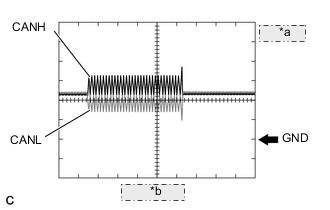
*a 1 V/DIV. *b 50 μs./DIV. Normal waveform
-
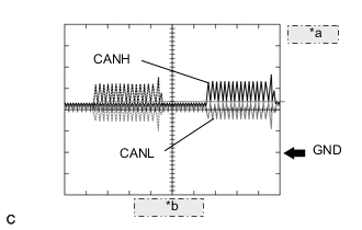
*a 1 V/DIV. *b 50 μs./DIV. Open in both of the lines (CANH and CANL) of a CAN branch
Tech Tips
-
Waveforms (waveforms shown using dotted lines) are not present from an ECU or sensor connected to a CAN branch with an open circuit in both lines. (Waveforms from other ECUs or sensors are normal.)
-
Because this waveform is similar to a normal waveform, instead of using the waveform, the malfunctioning part can be narrowed down by performing a CAN bus check.
-
-
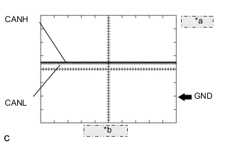
*a 1 V/DIV. *b 50 μs./DIV. Short between the CAN bus lines (CANH and CANL)
Tech Tips
-
Waveforms disappear.
-
If the malfunction is in an ECU, disconnecting the ECU will change the waveform. If the waveform does not change, a malfunction in the wire harness is suspected.
-
-
-
CAN bus waveforms (reference) (Group 2)
Note
The following CAN bus waveforms can be used only as reference. The actual measured waveform may differ significantly depending on the location of the open or short circuit.
-
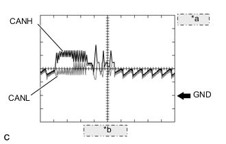
*a 1 V/DIV. *b 50 μs./DIV. Open in a CAN branch line (CANH)
Tech Tips
-
An abnormal waveform is output from an ECU with an open in one of its CAN branch lines. Because this abnormal output interferes with the signals from other ECUs, the output of other ECUs will also appear abnormal.
-
Narrow down the malfunctioning part by checking DTCs or performing a CAN bus check, or by checking waveform changes when ECUs or sensors are disconnected. The waveform will change to one for an open in both sides of a CAN branch when the ECU or sensor with an open CAN branch line is disconnected.
-
-
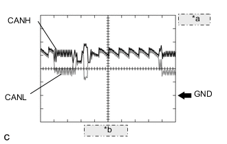
*a 1 V/DIV. *b 50 μs./DIV. Open in a CAN branch line (CANL)
Tech Tips
-
An abnormal waveform is output from an ECU with an open in one of its CAN branch lines. Because this abnormal output interferes with the signals from other ECUs, the output of other ECUs will also appear abnormal.
-
Narrow down the malfunctioning part by checking DTCs or performing a CAN bus check, or by checking waveform changes when ECUs or sensors are disconnected. The waveform will change to one for an open in both sides of a CAN branch when the ECU or sensor with an open CAN branch line is disconnected.
-
-
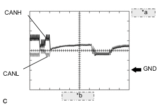
*a 1 V/DIV. *b 50 μs./DIV. Open in a CAN main bus line (CANH)
Tech Tips
-
Waveforms of ECUs or sensors that are closer to the DLC3 than the open part are almost normal.
-
Waveforms of ECUs or sensors that are on the opposite side of the DLC3 from the open part are abnormal.
-
An open in a CAN main bus line can be confirmed by measuring the resistance between the CANH and CANL terminals of any CAN branch.
-
-
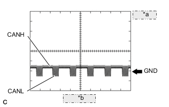
*a 1 V/DIV. *b 50 μs./DIV. Short between a CAN bus line (CANH) and ground
Tech Tips
-
Narrow down the shorted part by checking for waveform changes when disconnecting connectors from the CAN junction connectors or when disconnecting ECUs or sensors.
-
A short to ground in the CANH line can be confirmed by measuring the resistance between CANH and ground using an electrical tester.
-
-
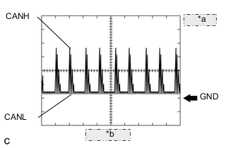
*a 1 V/DIV. *b 50 μs./DIV. Short between a CAN bus line (CANL) and ground
Tech Tips
-
Narrow down the shorted part by checking for waveform changes when disconnecting connectors from the CAN junction connectors or when disconnecting ECUs or sensors.
-
A short to ground in the CANL line can be confirmed by measuring the resistance between CANL and ground using an electrical tester.
-
-
-
-
DATA SENDING/RECEIVING TABLE
-
Data sending/receiving table
Tech Tips
If Data List items related to sent/received data are not displayed properly, the part for which communication is interrupted can be determined using the table below.
Data content Data Detected and Sent by Data Received from
(Can be Checked in Data List)
Data Received
(Cannot be Checked in Data List)
Selected System Relevant Data List Item Link Engine speed ECM
-
Combination meter assembly
-
Skid control ECU assembly
-
Power steering ECU assembly
-
Absorber control ECU
-
Certification ECU (smart key ECU assembly)
-
Combination meter mirror ECU
-
Airbag sensor assembly
-
Air conditioning amplifier assembly
-
Multi-media module receiver assembly
-
Main body ECU (multiplex network body ECU)
-
Certification ECU (smart key ECU assembly)
-
Front steering control ECU
-
Rear steering control ECU
-
Telematics transceiver
-
Parking brake ECU assembly
Engine Engine Speed
-
for 2GR-FXE: Click here
-
for 2AR-FSE (w/ EGR System): Click here
-
for 2AR-FSE (w/o EGR System): Click here
Combination Meter Engine Rpm ABS/VSC/TRC Engine Revolutions EMPS Engine Revolution
-
for 2GR-FXE: Click here
-
for 2AR-FSE: Click here
Air suspension Engine Speed Starting Control Engine Speed Head Up Display Engine Rpm Engine coolant temperature ECM
-
Air conditioning amplifier assembly
-
Combination meter assembly
-
Power steering ECU assembly
-
Certification ECU (smart key ECU assembly)
-
Multi-media module receiver assembly
-
Skid control ECU assembly
Engine Coolant Temp
-
for 2GR-FXE: Click here
-
for 2AR-FSE (w/ EGR System): Click here
-
for 2AR-FSE (w/o EGR System): Click here
Air Conditioner Engine Coolant Temp Combination Meter Coolant Temperature Shift position signal Power management control ECU
-
Parking brake ECU assembly
-
Clearance warning ECU assembly
-
Position control ECU assembly LH
-
Power seat switch assembly
-
Position control ECU assembly RH
-
Multi-media module receiver assembly
-
Blind spot monitor sensor RH
-
Luggage closer motor assembly
-
Multiplex network door ECU
-
Airbag sensor assembly
-
Main body ECU (multiplex network body ECU)
-
Headlight ECU sub-assembly LH
-
Combination meter assembly*1
-
Front steering control ECU
-
Telematics transceiver
-
Forward recognition camera
-
Combination meter mirror ECU
-
Driving support ECU assembly
Hybrid Control
-
Shift Sensor SW - P
-
Shift Sensor SW - R
-
Shift Sensor SW - N
-
Shift Sensor SW - D
-
for 2GR-FXE: Click here
-
for 2AR-FSE: Click here
Electric Parking Brake
-
P Position
-
N Position
-
R Position
-
D Position
Driver Seat Shift SW Position Passenger Seat Shift SW Position Clearance Sonar
-
Parking Signal
-
Reverse Signal
Navigation System Reverse Signal Blind Spot Monitor Master Reverse Stop light switch signal Skid control ECU assembly
-
Parking brake ECU assembly
-
Power management control ECU
-
Absorber control ECU
-
Luggage closer motor assembly
-
Multiplex network door ECU
-
Airbag sensor assembly
-
Multi-media module receiver assembly
-
Front steering control ECU
-
Rear steering control ECU
-
Telematics transceiver
-
Driving support ECU assembly
ABS/VSC/TRC Stop Light SW Electric Parking Brake Stop Light Switch Hybrid Control Stop Light Switch
-
for 2GR-FXE: Click here
-
for 2AR-FSE: Click here
Air suspension Stop Light Switch Vehicle speed Skid control ECU assembly
-
Power management control ECU
-
Parking brake ECU assembly
-
Power steering ECU assembly
-
Combination meter assembly
-
Front steering control ECU
-
Rear steering control ECU
-
Blind spot monitor sensor RH
-
Multi-media module receiver assembly
-
Steering angle sensor
-
Driving support ECU assembly
ABS/VSC/TRC Vehicle Speed Hybrid Control Vehicle Spd
-
for 2GR-FXE: Click here
-
for 2AR-FSE: Click here
Combination Meter Vehicle Speed Meter Electric Parking Brake Vehicle Speed EMPS Meter Vehicle Velocity
-
for 2GR-FXE: Click here
-
for 2AR-FSE: Click here
VGRS Vehicle Speed DRS Vehicle Speed Radar Cruise1 Cruise Vehicle Speed Blind Spot Monitor Master Vehicle Speed Vehicle speed Combination meter assembly*2
-
Position control ECU assembly LH
-
Power seat switch assembly
-
Position control ECU assembly RH
-
Multiplex tilt and telescopic ECU
-
Luggage closer motor assembly
-
Multiplex network door ECU
-
Air conditioning amplifier assembly
-
Main body ECU (multiplex network body ECU)
-
Certification ECU (smart key ECU assembly)
-
Clearance warning ECU assembly
-
Telematics transceiver
Combination Meter Vehicle Speed Meter Driver Seat Vehicle Speed Passenger Seat Vehicle Speed Tilt & Telescopic Freeze Speed Info Ambient temperature Air conditioning amplifier assembly
-
ECM
-
Combination meter assembly
-
Power management control ECU
-
Front steering control ECU
-
Multi-media module receiver assembly
-
Main body ECU (multiplex network body ECU)
-
Parking brake ECU assembly
-
Power steering ECU assembly
-
Skid control ECU assembly
-
Telematics transceiver
-
Forward recognition camera
-
Driving support ECU assembly
Air Conditioner Ambient Temp Sensor Engine Ambient Temp for A/C
-
for 2GR-FXE: Click here
-
for 2AR-FSE (w/ EGR System): Click here
-
for 2AR-FSE (w/o EGR System): Click here
Combination Meter Ambient Temperature Hybrid Control Ambient Temperature
-
for 2GR-FXE: Click here
-
for 2AR-FSE: Click here
VGRS Ambient Temperature Steering angle sensor Steering angle sensor
-
Power steering ECU assembly
-
Skid control ECU assembly
-
Front steering control ECU
-
Driving support ECU assembly
-
Blind spot monitor sensor RH
-
Absorber control ECU
-
Multi-media module receiver assembly
-
Airbag sensor assembly
-
Headlight ECU sub-assembly LH
-
Forward recognition camera
-
Combination meter assembly
-
ECM
EMPS Steering Angle
-
for 2GR-FXE: Click here
-
for 2AR-FSE: Click here
ABS/VSC/TRC Steering Angle Sensor VGRS Steering Angle Radar Cruise2 Steering Angle Blind Spot Monitor Master Steering Angle Air suspension Steering Angle Door courtesy switch signal Main body ECU (multiplex network body ECU) Position control ECU assembly RH
-
Multi-media module receiver assembly
-
Certification ECU (smart key ECU assembly)
-
Combination meter assembly
-
Front multiplex network door ECU RH
-
Front multiplex network door ECU LH
-
Telematics transceiver
-
Parking brake ECU assembly
-
Forward recognition camera
-
Skid control ECU assembly
Main Body
-
RR Door Courtesy SW
-
RL Door Courtesy SW
-
FR Door Courtesy SW
-
FL Door Courtesy SW
Passenger Seat P-Door Courtesy
-
*1: Whether the ECU that sends data is functioning or not can be judged by using the GTS to check items such as switches or sensors that send signals to the ECU via direct lines.
-
*2: The combination meter assembly receives a vehicle speed signal from the skid control ECU assembly and sends the signal to other ECUs.
-
-