STEERING LINKAGE DISASSEMBLY

PROCEDURE
-
FIX RACK AND PINION POWER STEERING GEAR ASSEMBLY
-
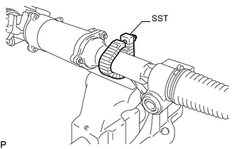
Using SST, secure the power steering link assembly.
- SST
- 09612-00012
Tech Tips
Tape SST before use.
-
-
REMOVE WIRE HARNESS CLAMP BRACKET
-
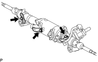
Remove the 3 bolts and 3 harness clamp brackets.
-
-
REMOVE TIE ROD ASSEMBLY LH
-
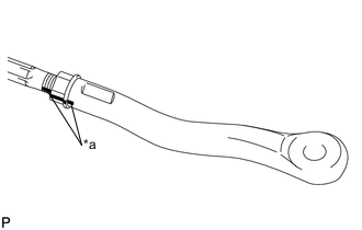
Text in Illustration *a Matchmark Put matchmarks on the tie rod end LH and steering rack end sub-assembly.
-
Loosen the lock nut and remove the tie rod end LH and lock nut.
-
-
REMOVE TIE ROD ASSEMBLY RH
Tech Tips
Use the same procedure as for the LH side.
-
REMOVE STEERING RACK BOOT CLIP
-
Using pliers, remove the 2 steering rack boot clips.
-
-
REMOVE NO. 1 STEERING RACK BOOT CLAMP
-
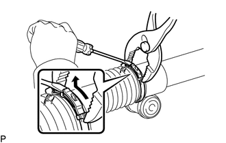
for Type A:
-
Using pliers, squeeze the No. 1 steering rack boot clamp.
-
Using a screwdriver, move the end of the No. 1 steering rack boot clamp as shown in the illustration to remove the No. 1 steering rack boot clamp.
Note
If the No. 1 steering rack boot is damaged when removing the No. 1 steering rack boot clamp, replace the No. 1 steering rack boot with a new one.
Tech Tips
Use the same procedure for the RH and LH sides.
-
-
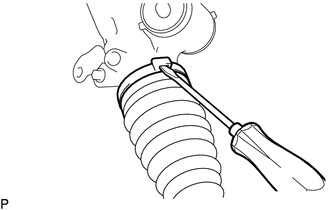
for Type B:
Using a screwdriver, unstake the No. 1 steering rack boot clamp to remove it.
Note
If the No. 1 steering rack boot is damaged when removing the No. 1 steering rack boot clamp, replace the No. 1 steering rack boot with a new one.
Tech Tips
Use the same procedure for the RH and LH sides.
-
-
REMOVE NO. 1 STEERING RACK BOOT
-
Remove the 2 steering rack boots.
Note
If there is rust, water or foreign matter inside either of the rack boots, replace the power steering assembly.
-