DYNAMIC REAR STEERING SYSTEM TERMINALS OF ECU
-
TERMINALS OF ECU
Tech Tips
The DRS ECU (rear steering control ECU) uses waterproof connectors. Therefore, checking the voltage at the terminals and checking the waveforms with an oscilloscope cannot be performed with the ECU installed to the vehicle.
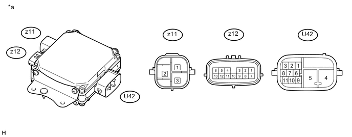
Text in Illustration *a Component without harness connected
(DRS ECU (Rear Steering Control ECU))
- - Terminal No. Symbol Terminal Description U42-2 CANH CAN communication input/output U42-3 CANL CAN communication input/output U42-4 PIG Motor power supply input U42-5 GNDY Power ground U42-8 CAN- Local CAN communication input/output U42-9 IGY IG power supply input U42-11 CAN+ Local CAN communication input/output z11-1 V V phase motor output z11-2 U U phase motor output z11-3 W W phase motor output z12-1 MSG2 Motor resolver sensor shielded ground z12-2 MRG Motor resolver sensor excitation circuit ground z12-3 MRV Motor resolver sensor excitation output z12-4 ARV Stroke sensor excitation output z12-5 ARG Stroke sensor excitation circuit ground z12-7 MS2 Motor resolver sensor SIN phase input z12-8 MS1 Motor resolver sensor COS phase input z12-12 AS1 Stroke sensor COS phase input z12-13 AS2 Stroke sensor SIN phase input -
CHECK DRS ECU (REAR STEERING CONTROL ECU)
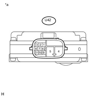
Text in Illustration *a Component without harness connected
(DRS ECU [Rear Steering Control ECU])
-
Disconnect the U42 DRS ECU (rear steering control ECU) connector.
-
Measure the resistance according to the value(s) in the table below.
Standard Terminal No. (Symbol) Wiring Color Terminal Description Condition Specified Condition U42-8 (CAN-) - U42-11 (CAN+) - Local CAN communication input/output Always 100 to 140 Ω
-
-
CHECK DRS ECU (REAR STEERING CONTROL ECU) WIRE HARNESS SIDE CONNECTOR
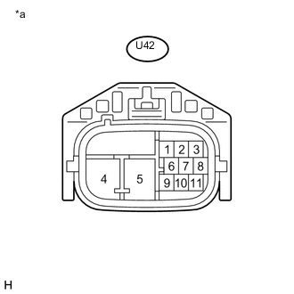
Text in Illustration *a Front view of wire harness connector
(to DRS ECU [Rear Steering Control ECU])
-
Disconnect the U42 DRS ECU (rear steering control ECU) connector.
-
Measure the voltage and resistance according to the value(s) in the table below.
Standard Terminal No. (Symbol) Wiring Color Terminal Description Condition Specified Condition U42-2 (CANH) - U42-3 (CANL) G - SB CAN communication input/output Power switch off 54 to 69 Ω U42-4 (PIG) - Body ground B - Body ground Motor power supply input Always 11 to 14 V U42-5 (GNDY) - Body ground W-B - Body ground Power ground Always Below 1 Ω U42-8 (CAN-) - U42-11 (CAN+) LG - W Local CAN communication input/output Power switch off 100 to 140 Ω U42-9 (IGY) - Body ground G - Body ground IG power supply input Power switch on (IG) 11 to 14 V
-
-
CHECK REAR STEERING LINK ASSEMBLY WIRE HARNESS SIDE CONNECTOR
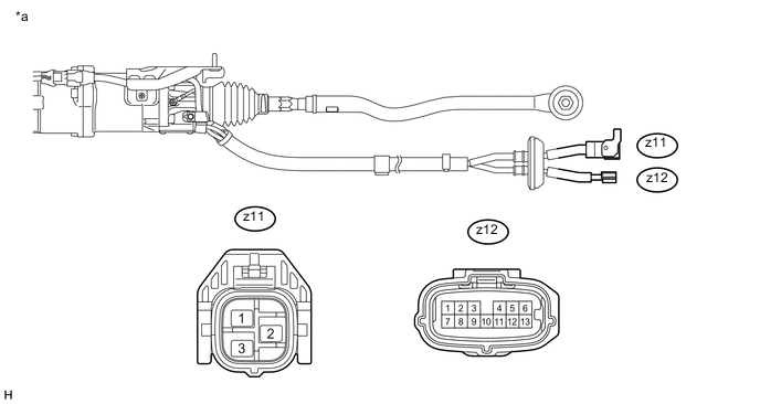
Text in Illustration *a Component without harness connected
(Rear Steering Link Assembly)
- -
-
Disconnect the rear steering link assembly connector from the DRS ECU (rear steering control ECU).
-
Measure the resistance according to the value(s) in the table below.
Standard Terminal No. (Symbol) Wiring Color Terminal Description Condition Specified Condition z11-1 (V) - z11-2 (U) or z11-3 (W) B - R or W V phase motor output Always Below 1 Ω z11-2 (U) - z11-1 (V) or z11-3 (W) R - B or W U phase motor output Always Below 1 Ω z11-3 (W) - z11-1 (V) or z11-2 (U) W - B or R W phase motor output Always Below 1 Ω z12-2 (MRG) - z12-3 (MRV) B - W Motor resolver sensor Always 26 to 64 Ω z12-2 (MRG) - z12-7 (MS2) B - G Motor resolver sensor Always 98 to 247 Ω z12-2 (MRG) - z12-8 (MS1) B - R Motor resolver sensor Always 92 to 230 Ω z12-3 (MRV) - z12-7 (MS2) W - G Motor resolver sensor Always 124 to 311 Ω z12-3 (MRV) - z12-8 (MS1) W - R Motor resolver sensor Always 118 to 294 Ω z12-7 (MS2) - z12-8 (MS1) G - R Motor resolver sensor Always 190 to 477 Ω z12-4 (ARV) - z12-5 (ARG) W - B Stroke sensor Always 5 to 50 Ω z12-4 (ARV) - z12-12 (AS1) W - R Stroke sensor Always 4 to 5 kΩ z12-4 (ARV) - z12-13 (AS2) W - G Stroke sensor Always 12 to 14.5 kΩ z12-5 (ARG) - z12-12 (AS1) B - R Stroke sensor Always 4 to 5 kΩ z12-5 (ARG) - z12-13 (AS2) B - G Stroke sensor Always 12 to 14.5 kΩ z12-12 (AS1) - z12-13 (AS2) R - G Stroke sensor Always 16 to 19 kΩ
-