POWER STEERING SYSTEM(for 2GR-FXE) CALIBRATION
-
MOTOR ROTATION ANGLE SENSOR VALUE INITIALIZATION AND TORQUE SENSOR ZERO POINT CALIBRATION (USING THE GTS)
Note
-
If the power steering link assembly or power steering ECU assembly is replaced, or there is a difference in steering effort between turning left and turning right, perform sensor calibration value initialization for the ECU, and then perform motor rotation angle sensor output calibration and torque sensor zero point calibration.
-
If C1516/16 (Torque Sensor Zero Point Adjustment Incomplete) is output, clear DTCs. Otherwise, torque sensor zero point calibration cannot be performed.
-
If C1526/18 (Rotation Angle Sensor Initialization Incomplete) is output, clear DTCs. Otherwise, motor rotation angle sensor output calibration cannot be performed.
-
Inspection before calibration.
-
Connect the GTS to the DLC3.
-
Turn the power switch on (IG).
-
Turn the GTS on.
-
Enter the following menus: Chassis / EMPS / Data List.
-
Check the IG power supply voltage on the GTS screen.
EMPS Tester Display Measurement Item/Range Normal Condition Diagnostic Note IG Power Supply ECU power source voltage/
Min.: 0.0000 V, Max.: 20.1531 V
Power switch on (IG): 11 to 14 V When a malfunction occurs, the problem may be the ECU power supply. Note
If the IG power supply voltage is below 9 V, calibration cannot be performed. In this case, charge or replace the auxiliary battery, and then perform calibration.
-
-
Clearing motor rotation angle sensor calibration value, motor rotation angle sensor value initialization and torque sensor zero point calibration.
-
Connect the GTS to the DLC3.
-
Turn the power switch on (IG).
-
Turn the GTS on.
-
Enter the following menus: Chassis / EMPS / Utility / Torque Sensor Adjustment.
-
Follow the procedures on the GTS display to clear the motor rotation angle sensor calibration value, initialize the motor rotation angle sensor value and calibrate the torque sensor zero point.
Note
-
When initializing the motor rotation angle sensor value, observe the following to stabilize sensor voltage:
After turning the power switch on (IG), wait for at least 2.5 seconds before turning the steering wheel. Do not turn the steering wheel quickly.
-
The steering wheel will vibrate during torque sensor zero point calibration. Do not touch the steering wheel while it is vibrating or for 2 seconds after it stops.
-
-
-
-
MOTOR ROTATION ANGLE SENSOR VALUE INITIALIZATION AND TORQUE SENSOR ZERO POINT CALIBRATION (USING SST CHECK WIRE)
Note
-
If the power steering link assembly or power steering ECU assembly is replaced, or there is a difference in steering effort between turning left and turning right, perform sensor calibration value initialization for the ECU, and then perform motor rotation angle sensor output calibration and torque sensor zero point calibration.
-
If C1516/16 (Torque Sensor Zero Point Adjustment Incomplete) is output, clear DTCs. Otherwise, torque sensor zero point calibration cannot be performed.
-
If C1526/18 (Rotation Angle Sensor Initialization Incomplete) is output, clear DTCs. Otherwise, motor rotation angle sensor output calibration cannot be performed.
-
Inspection before calibration.
-
Turn the power switch off.
-
Disconnect the power steering ECU connector.
-
Turn the power switch on (IG).
-
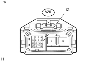
Text in Illustration *a Front view of wire harness connector
(to Power Steering ECU)
Measure the voltage between terminal 14 (IG) of connector A29 (the connector of the wire harness that connects to the power steering ECU) and body ground.
Note
If the IG power supply voltage is below 9 V, calibration cannot be performed. In this case, charge or replace the auxiliary battery, and then perform calibration.
-
Turn the power switch off.
-
Reconnect the power steering ECU connector.
-
-
Perform sensor calibration value initialization.
-
Align the front tires and steering wheel so that they are facing straight ahead.
-
Turn the power switch off.
-
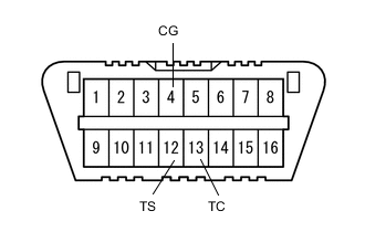
Using SST, connect terminals 12 (TS) and 4 (CG) of the DLC3, turn the power switch on (IG) and connect and disconnect terminals 13 (TC) and 4 (CG) of the DLC3 20 times or more within 20 seconds.
- SST
- 09843-18040
Note
Connect the terminals correctly to avoid a malfunction.
-
Check that the power steering warning light turns on.
Tech Tips
DTCs C1515/15 and C1525/17 are stored.
-
Turn the power switch off.
Note
If the power switch is left on (IG) after performing sensor calibration value initialization, motor rotation angle sensor output calibration and torque sensor zero point calibration cannot be performed.
-
-
Perform motor rotation angle sensor output calibration.
Note
If DTC C1525/17 (Rotation Angle Sensor Initialization Undone) is not stored, motor rotation angle sensor output calibration cannot be performed. Therefore, be sure to perform sensor calibration value initialization before performing motor rotation angle sensor output calibration.
Tech Tips
Motor rotation angle sensor output calibration calibrates the output values of the motor rotation angle sensor and torque sensor.
-
Align the front tires and steering wheel so that they are facing straight ahead.
-
Turn the power switch off.
-
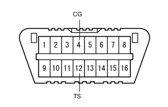
Using SST, connect terminals 12 (TS) and 4 (CG) of the DLC3, and then turn the power switch on (IG).
- SST
- 09843-18040
Note
Connect the terminals correctly to avoid a malfunction.
Tech Tips
If DTC C1525/17 is present when test mode starts, the system automatically switches to motor rotation angle sensor output calibration mode.
-
Turn the steering wheel 45° or more to the left and right.
Note
-
After turning the power switch on (IG), wait 2.5 seconds or more before turning the steering wheel in order to allow the sensor voltage to stabilize.
-
Do not turn the steering wheel quickly.
-
-
-
Perform torque sensor zero point calibration.
Note
-
If DTC C1525/17 (Rotation Angle Sensor Initialization Undone) is stored, torque sensor zero point calibration cannot be performed. Therefore, be sure to perform motor rotation angle sensor output calibration before performing torque sensor zero point calibration.
-
If DTC C1515/15 (Torque Sensor Zero Point Adjustment Undone) is not stored, torque sensor zero point calibration cannot be performed. Therefore, be sure to perform sensor calibration value initialization before performing torque sensor zero point calibration.
-
Align the front tires and steering wheel so that they are facing straight ahead.
-
Turn the power switch off.
-
Using SST, connect terminals 12 (TS) and 4 (CG) of the DLC3, turn the power switch on (IG) and connect terminals 13 (TC) and 4 (CG) of the DLC3.
Note
The steering wheel will vibrate during calibration. Do not touch the steering wheel while it is vibrating, and wait at least 2 seconds after the steering wheel stops vibrating before touching it.
Tech Tips
-
If the calibration is completed successfully, the power steering warning light changes from being constantly illuminated to blinking at a frequency of 4 Hz (repeating a pattern of being on for 0.125 seconds, and then off for 0.125 seconds).
-
If the calibration is not completed successfully, the power steering warning light remains illuminated.
-
If the calibration is not completed successfully, check for DTCs.
-
-
Disconnect terminals 12 (TS) and 4 (CG), and 13 (TC) and 4 (CG) of the DLC3, and then turn the power switch off to switch the system from test mode to normal mode.
-
-
-
ASSIST MAP WRITING (USING THE GTS)
Note
Perform assist map writing when the power steering ECU assembly is replaced.
Tech Tips
If the assist map is not recorded, DTC C1581/26 (Assist Map Un-Writing) is stored and the power steering warning light illuminates.
-
Turn the power switch off.
-
Connect the GTS to the DLC3.
-
Turn the power switch on (IG).
-
Turn the GTS on.
-
Enter the following menus: Chassis / EMPS / Utility / Signal Check.
-
Wait for 10 seconds or more.
-
Confirm that the power steering warning light changes from illuminated to blinking at 4 Hz (4 blinks per second).
Note
-
If the power steering warning light does not change from an illuminated state to blinking at 4 Hz (the assist map cannot be recorded), check for DTCs.
-
If only DTC C1581/26 (Assist Map Un-Writing) is stored, perform assist map writing again. However, if the assist map cannot be recorded even after performing the procedure 3 times, replace the power steering ECU and perform assist map writing.
-
If DTCs other than DTC C1581/26 (Assist Map Un-Writing) are stored, perform troubleshooting according to the diagnostic trouble code chart, and then perform assist map writing.
-
-
-
ASSIST MAP WRITING (USING SST CHECK WIRE)
Note
Perform assist map writing when the power steering ECU assembly is replaced.
Tech Tips
If the assist map is not recorded, DTC C1581/26 (Assist Map Un-Writing) is stored and the power steering warning light illuminates.
-
Turn the power switch off
-
Using SST, connect terminals 12 (TS) and 4 (CG) of the DLC3.
- SST
- 09843-18040
Note
Connect the terminals correctly to avoid a malfunction.
-
Turn the power switch on (IG).
-
Wait for 10 seconds or more.
-
Confirm that the power steering warning light changes from illuminated to blinking at 4 Hz (4 blinks per second).
Note
-
If the power steering warning light does not change from an illuminated state to blinking at 4 Hz (the assist map cannot be recorded), check for DTCs.
-
If only DTC C1581/26 (Assist Map Un-Writing) is stored, perform assist map writing again. However, if the assist map cannot be recorded even after performing the procedure 3 times, replace the power steering ECU and perform assist map writing.
-
If DTCs other than DTC C1581/26 (Assist Map Un-Writing) are stored, perform troubleshooting according to the diagnostic trouble code chart, and then perform assist map writing.
-
-
-
STEERING SENSOR ZERO POINT CALIBRATION
Tech Tips
-
The steering zero point may be cleared if any of the following operations is performed; disconnecting the auxiliary battery terminal, disconnecting the steering sensor connector or removing the fuses in the steering sensor system.
-
Even if the steering zero point is not stored, the power steering warning light does not illuminate.
-
Turn the power switch on (READY).
-
Slowly turn the steering wheel 360° clockwise and counterclockwise twice or three times.
-
Drive the vehicle at a speed of 35 km/h (22 mph) or more for 5 seconds or more.
-