VARIABLE GEAR RATIO STEERING SYSTEM CALIBRATION

| DTC Code | DTC Name |
|---|---|
| CALIBRATION |
CAUTION / NOTICE / HINT
Note
Use this procedure to center the steering wheel if:
-
The steering actuator assembly has been replaced.
-
The VGRS ECU (front steering control ECU) has been replaced.
-
The steering column assembly or steering intermediate shaft has been disconnected.
-
The front wheel alignment has been adjusted.
-
The steering wheel is still off-center after completing the steering sensor initialization.
PROCEDURE
-
VGRS SYSTEM CALIBRATION PROCEDURE
Result Proceed to USING SST CHECK WIRE USING GTS
USING GTS 
FACE TIRES STRAIGHT AHEAD Click here
USING SST CHECK WIRE 
-
FACE TIRES STRAIGHT AHEAD
Note
Drive the vehicle to confirm that the steering wheel is centered.
Result Proceed to NEXT
NEXT
-
CHECK DTC
-
Check for DTCs.
Result Result Proceed to DTC C1591/51 is not output A DTC C1591/51 is output B
B
GO TO STEP 5 Click here
A
-
-
PERFORM ACTUATOR ANGLE INITIALIZATION
Note
If the procedures from *1 to *2 are not completed within 1 minute, or if errors are made during these procedures, perform initialization again from the beginning.
-
Turn the power switch off.
-
Using SST, connect terminals 12 (TS) and 4 (CG) of the DLC3.*1
- SST
- 09843-18040
-
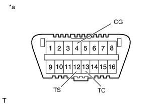
*a Front view of DLC3 Turn the power switch on (READY). Start the engine.
-
Center the steering wheel.
-
Using SST, connect terminals 13 (TC) and 4 (CG) of the DLC3.
-
Disconnect SST from terminal 12 (TS) of the DLC3 and turn the steering wheel to the left 180° or more.
-
Connect SST to terminal 12 (TS) of the DLC3.
-
Disconnect SST from terminal 13 (TC) of the DLC3 and turn the steering wheel to the right 180° or more.
-
Connect SST to terminal 13 (TC) of the DLC3.*2
Tech Tips
If the master warning light comes on, DTC C1591/51 is stored.
-
Disconnect SST from the DLC3.
-
Turn the power switch off.
Result Proceed to NEXT
NEXT
-
-
FACE TIRES STRAIGHT AHEAD
-
Confirm that the steering wheel is centered when facing the tires straight ahead.
Note
Drive the vehicle to confirm that the steering wheel is centered.
Result Result Proceed to Steering wheel is off-center A Steering wheel is centered B
B
GO TO STEP 9 Click here
A
-
-
UNLOCK STEERING ACTUATOR
Note
Unlock the steering actuator with the vehicle stopped.
-
Turn the power switch off.
-
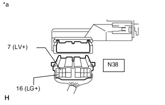
*a Rear view of wire harness connector
(to Steering Actuator Assembly)
Disconnect the cable from the negative (-) auxiliary battery terminal.
-
Disconnect the steering actuator assembly connector.
-
Connect a jumper wire from terminal 7 (LV+) of the steering actuator assembly to the positive (+) 12 V battery terminal and another jumper wire from terminal 16 (LG+) of the steering actuator assembly to the negative (-) 12 V battery terminal.
Note
Do not apply voltage for more than 3 minutes.
Result Proceed to NEXT
NEXT
-
-
STEERING CENTER ADJUSTMENT
-
Center the steering wheel.
Note
If the centering of the spiral cable sub-assembly was not confirmed when the steering wheel was installed, confirm the centering of the spiral cable.
Result Proceed to NEXT
NEXT
-
-
LOCK STEERING ACTUATOR
-
Disconnect the positive (+) and negative (-) 12 V battery jumper wires from the steering actuator assembly.
-
Connect the connector to the steering actuator assembly.
-
Connect the cable to the negative (-) auxiliary battery terminal.
-
Turn the steering wheel approximately 3° to the left and right. Confirm that the reaction force can be felt.
Note
Perform these procedures with the power switch off.
Result Proceed to NEXT
NEXT
-
-
ADJUST ACTUATOR ANGLE
Tech Tips
Activating and ending test mode completes the actuator angle adjustment.
-
Make sure the power switch is off.
Note
Do not touch the steering wheel during these procedures.
-
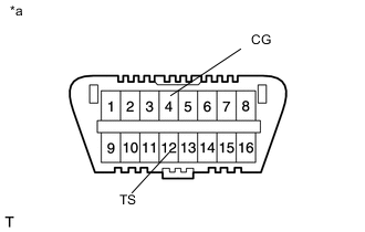
*a Front view of DLC3 Using SST, connect terminals 12 (TS) and 4 (CG) of the DLC3.
- SST
- 09843-18040
-
Turn the power switch on (IG).
-
Confirm that "VGRS Test Mode" is displayed on the multi-information display when test mode is activated.
Tech Tips
Wait approximately 5 seconds.
-
Turn the power switch off.
-
Disconnect SST from terminals 12 (TS) and 4 (CG) of the DLC3.
-
Turn the power switch on (IG) again.
Result Proceed to NEXT
NEXT
-
-
CHECK MASTER WARNING LIGHT
-
Confirm that the master warning light is off.
-
Turn the power switch off, and then on (IG).
-
Confirm that the master warning light is operating normally.
Result Proceed to NEXT
NEXT
-
-
CHECK STEERING WHEEL OPERATION
-
Turn the power switch on (READY).
-
Perform the steering sensor initialization.
-
Drive the vehicle and confirm that the steering wheel is centered.
Result Proceed to NEXT
NEXT 
END
-
-
FACE TIRES STRAIGHT AHEAD
Note
Drive the vehicle to confirm that the steering wheel is centered.
Result Proceed to NEXT
NEXT
-
PERFORM VGRS SYSTEM CALIBRATION
-
Connect the GTS to the DLC3.
-
Turn the power switch on (IG).
-
Turn the GTS on.
-
Enter the following menus: Chassis / VGRS / Utility / Steering Angle Adjust.
-
According to the display on the GTS, perform calibration.
Result Proceed to NEXT
NEXT
-
-
CHECK MASTER WARNING LIGHT
-
Confirm that the master warning light is off.
-
Turn the power switch off.
-
Disconnect the GTS from the DLC3.
-
Turn the power switch on (IG).
-
Confirm that the master warning light is operating normally.
Result Proceed to NEXT
NEXT
-
-
CHECK STEERING WHEEL OPERATION
-
Turn the power switch on (READY).
-
Perform the steering sensor initialization.
-
Drive the vehicle and confirm that the steering wheel is centered.
Result Proceed to NEXT
NEXT
END
-