ELECTRONICALLY CONTROLLED BRAKE SYSTEM Brake Control Warning Light Remains ON
DESCRIPTION
The skid control ECU assembly is connected to the combination meter assembly via CAN communication.
If the skid control ECU assembly stores a DTC, the brake warning light / yellow (minor malfunction) comes on in the combination meter assembly.
WIRING DIAGRAM
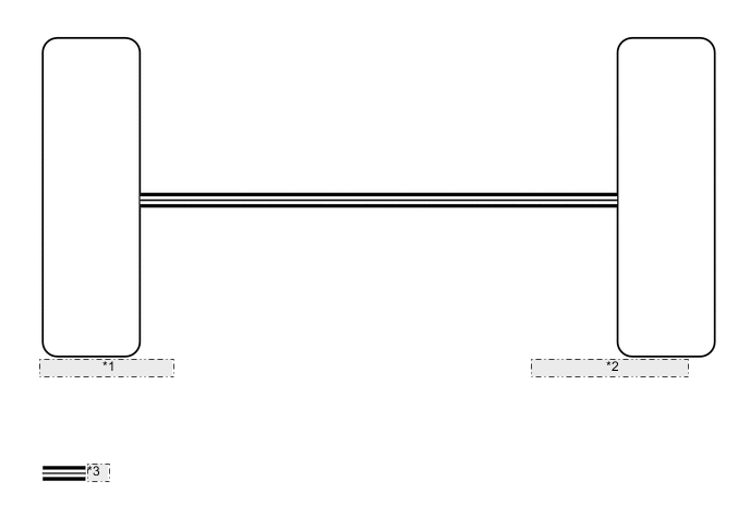
| *1 | Combination Meter Assembly |
| *2 | Skid Control ECU Assembly |
| *3 | CAN Communication System |
CAUTION / NOTICE / HINT
Note
When replacing the skid control ECU assembly, perform initialization and calibration of the linear solenoid valve Click here.
PROCEDURE
-
CHECK CAN COMMUNICATION SYSTEM
-
Check if a CAN communication system DTC is output (for LHD: See page , for RHD: Click here.
Result Result Proceed to DTC is not output A DTC is output (for LHD) B DTC is output (for RHD) C
B 
INSPECT CAN COMMUNICATION SYSTEM Click here
C
INSPECT CAN COMMUNICATION SYSTEM Click here
A 
-
-
CHECK IF SKID CONTROL ECU CONNECTOR IS SECURELY CONNECTED
-
Check if the skid control ECU assembly connector is securely connected.
OK The connector is securely connected.
NG
CONNECT CONNECTOR TO ECU CORRECTLY
OK
-
-
CHECK AUXILIARY BATTERY
-
Check the auxiliary battery voltage.
Standard Voltage Tester Connection Switch Condition Specified Condition Auxiliary battery Power switch on (IG) 11 to 14 V Auxiliary battery Power switch on (READY) 11 to 15.5 V
NG
CHARGE OR REPLACE AUXILIARY BATTERY
OK
-
-
INSPECT COMBINATION METER ASSEMBLY
-
Perform the Active Test of the combination meter assembly (meter CPU) using the GTS Click here.
-
Check the combination meter assembly.
OK The brake warning light / yellow (minor malfunction) turns on or off in accordance with the GTS operation. Tech Tips
If troubleshooting has been carried out according to Problem Symptoms Table refer back to the table and proceed to the next step before replacing the part Click here.
OK
REPLACE SKID CONTROL ECU ASSEMBLY Click here
NG
REPLACE COMBINATION METER ASSEMBLY Click here
-