ELECTRONICALLY CONTROLLED BRAKE SYSTEM, Diagnostic DTC:C1231

| DTC Code | DTC Name |
|---|---|
| C1231 | Steering Angle Sensor Circuit |
DESCRIPTION
The skid control ECU assembly inputs steering sensor signals via the CAN communication. When a malfunction occurs in the communication line with the steering sensor, DTC U0126 (Lost Communication with Steering Angle Sensor Module) is output.
| DTC Code | INF Code | DTC Detection Condition | Trouble Area |
|---|---|---|---|
| C1231 | 341 | Steering sensor stuck malfunction. |
|
| ↑ | 343 | Steering sensor malfunction signal is received when data transmission is valid (internal malfunction is detected in sensor self check). | Steering sensor |
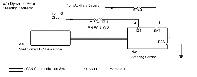
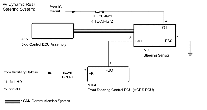
WIRING DIAGRAM
CAUTION / NOTICE / HINT
Note
Inspect the fuses for circuits related to this system before performing the following inspection procedure.
Tech Tips
-
When U0126 is output together with C1231, inspect and repair the trouble areas indicated by U0126 first Click here.
-
When the speed sensor or the yaw rate sensor is malfunctioning, DTCs for the steering angle sensor may be output even when the steering sensor is normal. When DTCs for the speed sensor or yaw rate sensor are output together with DTCs for the steering angle sensor, inspect and repair the speed sensor and yaw rate sensor first, and then inspect and repair the steering sensor.
PROCEDURE
-
CHECK DTC
-
Clear the DTCs Click here.
-
Turn the power switch off.
-
Turn the power switch on (IG) again and check that no CAN communication system DTC is output (for LHD: See page , for RHD: Click here.
-
Drive the vehicle at a speed of 35 km/h (22 mph) and turn the steering wheel to the right and left and check that no speed sensor and/or yaw rate sensor DTCs are output Click here.
Result Result Proceed to No CAN communication system, speed sensor, yaw rate sensor DTCs are output A CAN communication system DTC is output (for LHD) B CAN communication system DTC is output (for RHD) C Speed sensor and/or yaw rate sensor DTC is output D Tech Tips
-
If there is a malfunction in the speed sensor or the yaw rate sensor, an abnormal value may be output although the steering sensor is normal.
-
If speed sensor and yaw rate sensor DTCs are output simultaneously, repair these 2 sensors and inspect the steering sensor.
-
B 
INSPECT CAN COMMUNICATION SYSTEM Click here
C
INSPECT CAN COMMUNICATION SYSTEM Click here
D
REPAIR CIRCUITS INDICATED BY OUTPUT DTCS Click here
A 
-
-
CHECK HARNESS AND CONNECTOR (POWER SOURCE TERMINAL)
-
Turn the power switch off.
-
Remove the steering wheel and the column cover.
-
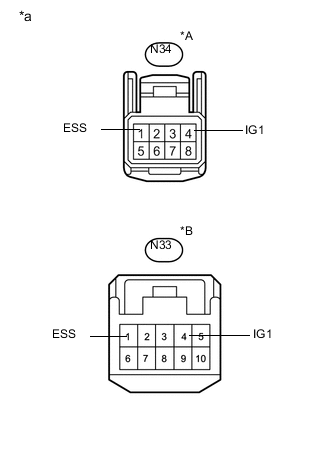
Text in Illustration *A w/o Dynamic Rear Steering System *B w/ Dynamic Rear Steering System *a Front view of wire harness connector
(to Steering Sensor)
Make sure that there is no looseness at the locking part and the connecting part of the connector.
-
Disconnect the steering sensor connector.
-
Measure the voltage according to the value(s) in the table below.
Standard Voltage w/o Dynamic Rear Steering System Tester Connection Switch Condition Specified Condition N34-4 (IG1) - Body ground Power switch on (IG) 11 to 14 V w/ Dynamic Rear Steering System Tester Connection Switch Condition Specified Condition N33-4 (IG1) - Body ground Power switch on (IG) 11 to 14 V -
Measure the resistance according to the value(s) in the table below.
Standard Resistance w/o Dynamic Rear Steering System Tester Connection Condition Specified Condition N34-1 (ESS) - Body ground Always Below 1 Ω w/ Dynamic Rear Steering System Tester Connection Condition Specified Condition N33-1 (ESS) - Body ground Always Below 1 Ω Result Result Proceed to NG A OK (w/o Dynamic Rear Steering System) B OK (w/ Dynamic Rear Steering System) C
A
REPAIR OR REPLACE HARNESS OR CONNECTOR
C 
CHECK HARNESS AND CONNECTOR (POWER SOURCE TERMINAL) Click here
B
-
-
CHECK HARNESS AND CONNECTOR (POWER SOURCE TERMINAL)
-
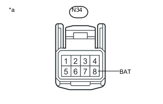
Text in Illustration *a Front view of wire harness connector
(to Steering Sensor)
Measure the voltage according to the value(s) in the table below.
Standard Voltage Tester Connection Condition Specified Condition N34-8 (BAT) - Body ground Always 11 to 14 V Tech Tips
If troubleshooting has been carried out according to Problem Symptoms Table, refer back to the table and proceed to the next step Click here.
OK
REPLACE STEERING SENSOR Click here
NG
REPAIR OR REPLACE HARNESS OR CONNECTOR (POWER SOURCE CIRCUIT)
-
-
CHECK HARNESS AND CONNECTOR (POWER SOURCE TERMINAL)
-
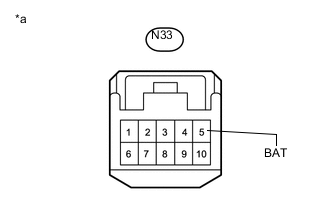
Text in Illustration *a Front view of wire harness connector
(to Steering Sensor)
Measure the voltage according to the value(s) in the table below.
Standard Voltage Tester Connection Condition Specified Condition N33-5 (BAT) - Body ground Always 11 to 14 V Tech Tips
If troubleshooting has been carried out according to Problem Symptoms Table, refer back to the table and proceed to the next step Click here.
OK
REPLACE STEERING SENSOR Click here
NG
-
-
CHECK HARNESS AND CONNECTOR (FRONT STEERING CONTROL ECU - STEERING SENSOR)
-
Disconnect the N104 front steering control ECU connector.
-
Measure the resistance according to the value(s) in the table below.
Standard Resistance Tester Connection Condition Specified Condition N104-1 (+BO) - N33-5 (BAT) Always Below 1 Ω N104-1 (+BO) - Body ground Always 10 kΩ or higher
NG
REPAIR OR REPLACE HARNESS OR CONNECTOR
OK
-
-
CHECK HARNESS AND CONNECTOR
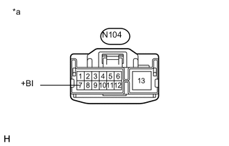
Text in Illustration *a Front view of wire harness connector
(to Front Steering Control ECU)
-
Measure the voltage according to the value(s) in the table below.
Standard Voltage Tester Connection Condition Specified Condition N104-7 (+BI) - Body ground Always 11 to 14 V Tech Tips
If troubleshooting has been carried out according to Problem Symptoms Table, refer back to the table and proceed to the next step Click here.
OK
REPLACE FRONT STEERING CONTROL ECU Click here
NG
REPAIR OR REPLACE HARNESS OR CONNECTOR (POWER SOURCE CIRCUIT)
-