GRILLE SHUTTER SYSTEM TERMINALS OF ECU
-
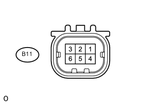
SWING GRILLE ACTUATOR ASSEMBLY
-
Disconnect the B11 swing grille actuator assembly connector.
-
Measure the voltage and resistance according to the value(s) in the table below.
Terminal No. (Symbol) Wiring Color Terminal Description Condition Specified Condition B11-6 (+B) - Body ground GR - Body ground Battery Always 11 to 14 V B11-4 (GND) - Body ground W-B - Body ground Ground Always Below 1 Ω If the result is not as specified, there may be a malfunction on the wire harness side.
-
Reconnect the B11 swing grille actuator assembly connector.
-
Measure the voltage according to the value(s) in the table below.
Tech Tips
A waterproof connector is connected to the swing grille actuator assembly. As a result, when performing an inspection on the swing grille actuator assembly, measure at the connector on the air conditioning amplifier assembly side with the connector connected.
Terminal No. (Symbol) Wiring Color Terminal Description Condition Specified Condition B11-2 (LIN) - Body ground G - Body ground Pulse generation Power switch on (IG) Pulse generation
-