ELECTRONICALLY CONTROLLED BRAKE SYSTEM INITIALIZATION

-
DESCRIPTION
-
Perform initialization and calibration of the linear solenoid valve when the skid control ECU assembly, brake actuator assembly or brake pedal stroke sensor assembly is replaced.
Follow the procedure to perform initialization.
Tech Tips
-
If there is a problem with the auxiliary battery (12 V) voltage, initialization and calibration of the linear solenoid valve cannot be completed normally. Make sure to check the auxiliary battery voltage before performing initialization and calibration of the linear solenoid valve.
-
If the actuator's temperature is high, initialization and calibration of the linear solenoid valve may not be completed normally. If so, wait until the temperature decreases and then perform initialization and calibration of the linear solenoid valve.
-
If the power switch is turned off, the brake pedal is depressed or vehicle speed signal is input while the linear solenoid valve offset learning is being performed, the learning will be canceled.
Part to be Replaced Necessary Operation Skid control ECU assembly Initialization and calibration of the linear solenoid valve Brake actuator assembly
-
Bleed air
-
Clearing stored linear solenoid valve calibration data
-
Initialization and calibration of the linear solenoid valve
-
Brake pedal stroke sensor assembly
-
Brake pedal
-
Clearing stored linear solenoid valve calibration data
-
Initialization and calibration of the linear solenoid valve
-
-
-
PERFORM INITIALIZATION AND CALIBRATION OF LINEAR SOLENOID VALVE (When Using the GTS)
-
Clear the stored linear solenoid valve calibration data.
-
Turn the power switch off.
-
Check that the steering wheel is centered.
-
Check that the shift lever is in P.
-
Connect the GTS to the DLC3.
-
Turn the power switch on (IG).
-
Turn the GTS on.
-
Select the skid control ECU assembly to clear the linear solenoid valve calibration data using the GTS. Enter the following menus: Chassis / ABS/VSC/TRC / Utility / Reset Memory.
-
-
Perform initialization and calibration of the linear solenoid valve.
-
Turn the power switch off.
-
Check that the steering wheel is centered.
-
Check that the shift lever is in P.
-
Connect the GTS to the DLC3.
-
Turn the power switch on (IG) with the brake pedal released.
Note
-
If the linear solenoid valve offset learning is performed without turning the power switch on (IG), the learning process may not be completed properly because of insufficient auxiliary battery voltage.
-
When the linear solenoid valve offset learning is interrupted, or the learning process is performed with the shift lever not in P, DTC C1345 (Linear Solenoid Valve Offset Learning Undone) will be stored.
-
-
Turn the GTS on.
-
Switch the skid control ECU assembly to the Test Mode using the GTS. Enter the following menus: Chassis / ABS/VSC/TRC / Utility / ECB* Utility / Linear Valve Offset.
*: Electronically Controlled Brake System
-
Leave the vehicle stationary without depressing the brake pedal for 2 minutes.
-
Check that the interval between blinks of the brake warning light / yellow (minor malfunction) changes from 1 second to 0.25 seconds.
Tech Tips
-
The time needed to complete initialization and calibration of the linear solenoid valve varies depending on auxiliary battery voltage.
-
The brake warning light / yellow (minor malfunction) blinks at 1 second intervals during initialization and calibration of the linear solenoid valve. After initialization and calibration are complete, the brake warning light / yellow (minor malfunction) changes to the Test Mode display and blinks at 0.25 second intervals.
-
-
Check that DTC C1345 (Linear Solenoid Valve Offset Learning Undone) which indicates trouble with stroke sensor zero point learning is not output when the brake warning light / yellow (minor malfunction) changes to the Test Mode display upon initialization and calibration of the linear solenoid valve completion.
-
Perform the zero point calibration of yaw rate and acceleration sensor Click here.
-
Enter the normal mode from the Test Mode following the GTS directions.
Tech Tips
Refer to the GTS operator's manual for further details.
-
-
-
PERFORM INITIALIZATION AND CALIBRATION OF LINEAR SOLENOID VALVE (When not Using the GTS)
-
Clear the stored linear solenoid valve calibration data.
-
Turn the power switch off.
-
Check that the steering wheel is centered.
-
Check that the shift lever is in P.
-
Turn the power switch on (IG) with the brake pedal released.
-

Text in Illustration *a Front view of DLC3 Using SST, connect and disconnect terminals TS and CG of the DLC3 4 times or more within 8 seconds.
- SST
- 09843-18040
-
Check that no codes other than ABS code 42, VSC code 45 and electronically controlled brake system code 48, 66, or 95 are stored in the diagnostic system.
Tech Tips
-
How to read DTCs:
Diagnostic trouble codes are represented by the number of blinks of a warning light. For example, code 21 would be shown by 2 blinks, a pause of 1.5 seconds, and then 1 blink.
-
If one code is detected:
The light repeats the same code after a pause of 4 seconds.
-
If multiple codes are detected:
The light outputs one code after another with a 2.5-second pause between each code. When all codes have been output, there is a 4-second pause and then the light begins to output the codes again.
-
The ABS warning, brake warning / yellow (minor malfunction) and slip indicator lights do not indicate a normal system code.
-
-
-
Perform initialization and calibration of the linear solenoid valve.
-
Turn the power switch off.
-
Check that the steering wheel is centered.
-
Check that the shift lever is in P.
-
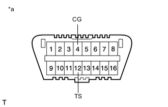
Text in Illustration *a Front view of DLC3 Using SST, connect terminals TS and CG of the DLC3.
- SST
- 09843-18040
-
Turn the power switch on (IG) with the brake pedal released.
Note
-
If the linear solenoid valve offset learning is performed without turning the power switch on (IG), the learning process may not be completed properly because of insufficient auxiliary battery voltage.
-
When the linear solenoid valve offset learning is interrupted, or the learning process is performed with the shift lever not in P, DTC 66 (Linear Solenoid Valve Offset Learning Undone) will be stored.
-
-
Leave the vehicle stationary without depressing the brake pedal for 2 minutes.
-
Check that the interval between blinks of the brake warning light / yellow (minor malfunction) changes from 1 second to 0.25 seconds.
Tech Tips
-
The time needed to complete initialization and calibration of the linear solenoid valve varies depending on the auxiliary battery voltage.
-
The brake warning light / yellow (minor malfunction) blinks at 1 second intervals during initialization and calibration of the linear solenoid valve. After initialization and calibration are complete, the brake warning light / yellow (minor malfunction) changes to the Test Mode display and blinks at 0.25 second intervals.
-
-
Check that DTC 66 (Linear Solenoid Valve Offset Learning Undone) which indicates trouble with stroke sensor zero point learning is not output when the brake warning light / yellow (minor malfunction) changes to the Test Mode display upon initialization and calibration of the linear solenoid valve completion.
-
Perform the zero point calibration of yaw rate and acceleration sensor Click here.
-
Turn the power switch off and disconnect SST from the DLC3.
-
-