REAR LOWER ARM INSTALLATION
PROCEDURE
-
TEMPORARILY INSTALL REAR NO. 2 SUSPENSION ARM ASSEMBLY
-
Temporarily install the rear No. 2 suspension arm assembly to the rear suspension member with the bolt, nut and washer.
Note
Insert the bolt with the threaded end facing the front of the vehicle.
-
Install the rear lower coil spring insulator to the rear No. 2 suspension arm.
-
Install the rear upper coil spring insulator to the rear coil spring.
-
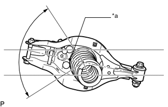
Text in Illustration *a Identification Mark Temporarily install the rear coil spring to the rear No. 2 suspension arm.
Note
Make sure that the identification mark is positioned towards the lower and outer sides of the vehicle.
-
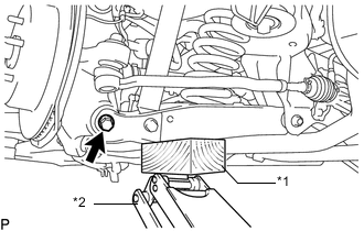
Text in Illustration *1 Wooden Block *2 Jack Using a jack and wooden block, raise the vehicle gradually to install the rear No. 2 suspension arm to the rear axle carrier. Then temporarily install the bolt and nut.
Note
-
Insert the bolt with the threaded end facing the rear of the vehicle.
-
When jacking up the rear No. 2 suspension arm assembly, be sure to jack it up slowly.
-
Do not jack up the rear No. 2 suspension arm assembly too high as the vehicle may fall.
-
Make sure to perform this operation with the vehicle kept as low as possible.
-
-
-
INSTALL REAR SUSPENSION MEMBER BRACE
-
Install the rear suspension member brace with the 2 new bolts.
- Torque:
- 56 N*m { 571 kgf*cm, 41 ft.*lbf }
-
-
TEMPORARILY INSTALL REAR SHOCK ABSORBER ASSEMBLY
-
INSTALL REAR STABILIZER LINK ASSEMBLY
-
TEMPORARILY INSTALL REAR NO. 1 SUSPENSION ARM ASSEMBLY
-
Temporarily install the rear No. 1 suspension arm assembly to the rear suspension member with the bolt and nut.
Note
Insert the bolt with the threaded end facing the rear of the vehicle.
-
Temporarily install the rear No. 1 suspension arm assembly to the axle carrier with the bolt and nut.
Note
Insert the bolt with the threaded end facing the rear of the vehicle.
-
-
CONNECT TOE CONTROL LINK SUB-ASSEMBLY (w/o DYNAMIC REAR STEERING)
-
CONNECT REAR STEERING LINK ASSEMBLY (w/ DYNAMIC REAR STEERING)
-
STABILIZE SUSPENSION
-
TIGHTEN REAR SHOCK ABSORBER ASSEMBLY
-
TIGHTEN REAR NO. 1 SUSPENSION ARM ASSEMBLY
-
Tighten the nut of the rear No. 1 suspension arm assembly for the suspension member side.
- Torque:
- 90 N*m { 918 kgf*cm, 66 ft.*lbf }
-
Tighten the bolt of the rear No. 2 suspension arm assembly for the rear axle assembly side.
- Torque:
- 90 N*m { 918 kgf*cm, 66 ft.*lbf }
-
-
TIGHTEN REAR NO. 2 SUSPENSION ARM ASSEMBLY
-
Tighten the nut of the rear No. 2 suspension arm assembly for the suspension member side.
- Torque:
- 150 N*m { 1530 kgf*cm, 111 ft.*lbf }
-
Tighten the bolt of the rear No. 2 suspension arm assembly for the rear axle assembly side.
- Torque:
- 145 N*m { 1479 kgf*cm, 107 ft.*lbf }
-
-
INSTALL REAR SUSPENSION ARM COVER
-
CONNECT REAR HEIGHT CONTROL SENSOR SUB-ASSEMBLY
-
INSTALL REAR WHEEL
-
INSPECT AND ADJUST REAR WHEEL ALIGNMENT
-
HEADLIGHT AIMING ADJUSTMENT
-
for Triple Beam Headlight:
-
for Single Beam Headlight:
-