REAR SUSPENSION MEMBER REMOVAL

PROCEDURE
-
RELEASE PARKING BRAKE
-
PRECAUTION
-
REMOVE LUGGAGE COMPARTMENT FLOOR MAT
-
REMOVE LUGGAGE COMPARTMENT TRIM COVER LH
-
DISCONNECT CABLE FROM NEGATIVE AUXILIARY BATTERY TERMINAL
-
REMOVE REAR WHEEL
-
DISCONNECT WIRE HARNESS
-
REMOVE NO. 1 FLOOR UNDER COVER
-
DISCONNECT PARKING BRAKE CABLE
-
REMOVE PARKING BRAKE CABLE HEAT INSULATOR
-
REMOVE ELECTRIC PARKING BRAKE ACTUATOR CAP
-
REMOVE PROPELLER WITH CENTER BEARING SHAFT ASSEMBLY
-
REMOVE REAR HEIGHT CONTROL SENSOR SUB-ASSEMBLY
-
DISCONNECT REAR SPEED SENSOR LH
-
DISCONNECT REAR SPEED SENSOR RH
Tech Tips
Use the same procedure described for the LH side.
-
REMOVE REAR AXLE SHAFT NUT LH
-
REMOVE REAR AXLE SHAFT NUT RH
Tech Tips
Use the same procedure described for the LH side.
-
REMOVE PARKING BRAKE
-
REMOVE TOE CONTROL LINK SUB-ASSEMBLY LH (w/o DYNAMIC REAR STEERING)
-
REMOVE TOE CONTROL LINK SUB-ASSEMBLY RH (w/o DYNAMIC REAR STEERING)
Tech Tips
Use the same procedure described for the LH side.
-
DISCONNECT REAR STEERING TIE ROD ASSEMBLY LH (w/ DYNAMIC REAR STEERING)
-
DISCONNECT REAR STEERING TIE ROD ASSEMBLY RH (w/ DYNAMIC REAR STEERING)
Tech Tips
Use the same procedure described for the LH side.
-
REMOVE REAR STEERING LINK ASSEMBLY (w/ DYNAMIC REAR STEERING)
-
REMOVE REAR SUSPENSION ARM COVER LH
-
REMOVE REAR SUSPENSION ARM COVER RH
Tech Tips
Use the same procedure described for the LH side.
-
REMOVE REAR NO. 1 SUSPENSION ARM ASSEMBLY LH
-
REMOVE REAR NO. 1 SUSPENSION ARM ASSEMBLY RH
Tech Tips
Use the same procedure described for the LH side.
-
REMOVE REAR STABILIZER LINK ASSEMBLY LH
-
REMOVE REAR STABILIZER LINK ASSEMBLY RH
Tech Tips
Use the same procedure described for the LH side.
-
DISCONNECT REAR SHOCK ABSORBER ASSEMBLY LH
-
DISCONNECT REAR SHOCK ABSORBER ASSEMBLY RH
Tech Tips
Use the same procedure described for the LH side.
-
REMOVE REAR SUSPENSION MEMBER BRACE LH
-
REMOVE REAR SUSPENSION MEMBER BRACE RH
Tech Tips
Use the same procedure described for the LH side.
-
REMOVE REAR NO. 2 SUSPENSION ARM ASSEMBLY LH
-
REMOVE REAR NO. 2 SUSPENSION ARM ASSEMBLY RH
Tech Tips
Use the same procedure described for the LH side.
-
REMOVE REAR NO. 1 UPPER CONTROL ARM ASSEMBLY (for LH Side)
-
REMOVE REAR NO. 1 UPPER CONTROL ARM ASSEMBLY (for RH Side)
Tech Tips
Use the same procedure described for the LH side.
-
REMOVE REAR UPPER CONTROL ARM ASSEMBLY LH
-
REMOVE REAR UPPER CONTROL ARM ASSEMBLY RH
Tech Tips
Use the same procedure described for the LH side.
-
REMOVE REAR AXLE ASSEMBLY LH
-
REMOVE REAR AXLE ASSEMBLY RH
Tech Tips
Use the same procedure described for the LH side.
-
REMOVE REAR SUSPENSION MEMBER BRACE
-
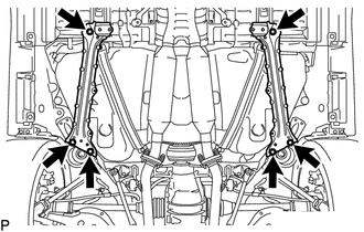
Remove the 6 bolts and 2 rear suspension member braces from the rear suspension member.
-
-
REMOVE REAR SUSPENSION MEMBER SUB-ASSEMBLY
-
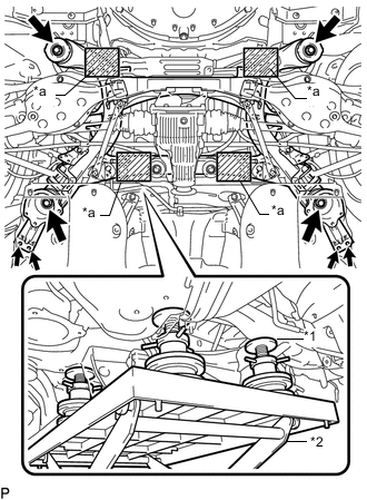
Text in Illustration *1 Attachment *2 Engine Lifter *a Attachment placement location Support the rear suspension member sub-assembly with an engine lifter using 4 attachments or equivalent tools as shown in the illustration.
Note
-
Use the attachments to keep the rear suspension member sub-assembly level.
-
The rear suspension member sub-assembly is a heavy component. Make sure that it is supported securely.
-
-
Remove the 6 bolts, 2 rear suspension member lower stoppers and 2 rear suspension member lower stopper sub-assemblies.
-
Slowly lower the rear suspension member sub-assembly.
Note
When lowering the rear suspension member sub-assembly, be careful not to damage the vehicle body or other components installed on the vehicle.
-
-
REMOVE PARKING BRAKE WITH BRACKET ACTUATOR ASSEMBLY
-
REMOVE REAR DIFFERENTIAL CARRIER ASSEMBLY
-
REMOVE REAR NO. 1 DIFFERENTIAL MOUNT CUSHION
-
REMOVE REAR NO. 2 DIFFERENTIAL MOUNT CUSHION
-
REMOVE REAR STABILIZER BAR
-
REMOVE REAR SUSPENSION MEMBER REAR LOWER STOPPER (for LH Side)
-
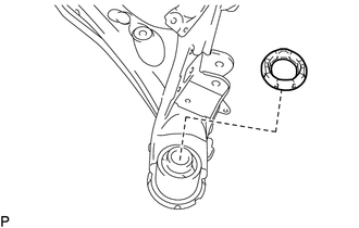
Remove the rear suspension member rear lower stopper from the rear suspension member sub-assembly.
-
-
REMOVE REAR SUSPENSION MEMBER REAR LOWER STOPPER (for RH Side)
Tech Tips
Use the same procedure described for the LH side.
-
REMOVE REAR SUSPENSION MEMBER FRONT BODY MOUNTING CUSHION (for LH Side)
-
Using a chisel and hammer, bend the rear suspension member rear body mounting cushion rib.
-
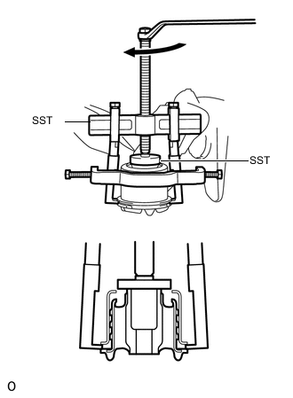
Using SST, remove the rear suspension member front body mounting cushion while applying grease into the clearance between the rear suspension member front body mounting cushion and the rear suspension member sub-assembly.
- SST
- 09950-40011 ( 09951-04020, 09952-04010, 09953-04030, 09954-04020, 09955-04061, 09957-04010, 09958-04011 )
- 09950-60010 ( 09951-00320 )
Note
-
Apply grease to the threads and tip of SST center bolt before use.
-
Be careful as the rear suspension member front body mounting cushion may fly out.
-
The rear suspension member front body mounting cushion cannot be reused.
-
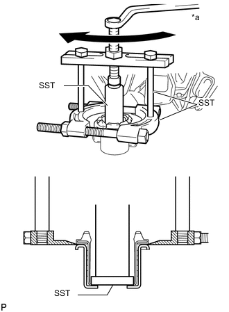
Text in Illustration *a Turn If the outer casing of the rear suspension member front body mounting cushion remains, insert SST between the rear suspension member front body mounting cushion and the rear suspension member sub-assembly, and then remove the outer casing.
- SST
- 09608-06041
- 09950-00020
- 09950-00030
- 09950-60010 ( 09951-00550 )
-
-
REMOVE REAR SUSPENSION MEMBER FRONT BODY MOUNTING CUSHION (for RH Side)
Tech Tips
Use the same procedure described for the LH side.
-
REMOVE REAR SUSPENSION MEMBER REAR UPPER STOPPER (for LH Side)
-
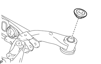
Remove the rear suspension member rear upper stopper from the rear suspension member sub-assembly.
-
-
REMOVE REAR SUSPENSION MEMBER REAR UPPER STOPPER (for RH Side)
Tech Tips
Use the same procedure described for the LH side.
-
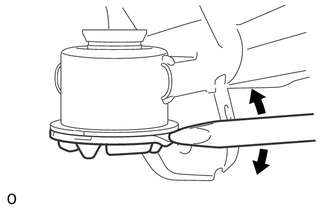
REMOVE REAR SUSPENSION MEMBER REAR BODY MOUNTING CUSHION (for LH Side)
-
Using a chisel and hammer, bend the rear suspension member rear body mounting cushion rib.
-
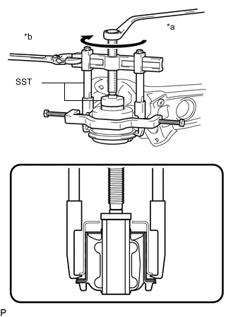
Text in Illustration *a Turn *b Hold Using SST, remove the rear suspension member rear body mounting cushion while applying grease into the clearance between the rear suspension member rear body mounting cushion and the rear suspension member sub-assembly.
- SST
- 09950-40011 ( 09951-04020, 09952-04010, 09953-04030, 09954-04020, 09955-04061, 09957-04010, 09958-04011 )
- 09950-60010 ( 09951-00320 )
Note
-
Apply grease to the threads and tip of SST center bolt before use.
-
Be careful as the rear suspension member rear body mounting cushion may fly out.
-
The rear suspension member rear body mounting cushion cannot be reused.
-
-
REMOVE REAR SUSPENSION MEMBER REAR BODY MOUNTING CUSHION (for RH Side)
Tech Tips
Use the same procedure described for the LH side.