PROPELLER SHAFT ASSEMBLY REASSEMBLY

CAUTION / NOTICE / HINT
Note
-
When using a vise, place aluminum plates between the part and vise.
-
When using a vise, do not overtighten it.
PROCEDURE
-
INSTALL NO. 1 CENTER SUPPORT BEARING ASSEMBLY
-
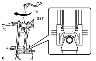
Text in Illustration *a Turn *b Hold Using SST, install a new No. 1 propeller shaft dust deflector.
- SST
- 09316-60011 ( 09316-00011 )
- 09506-35010
- 09950-40011 ( 09951-04020, 09952-04010, 09953-04030, 09954-04030, 09955-04021, 09958-04011 )
Note
Be careful not to damage the No. 1 propeller shaft dust deflector.
-
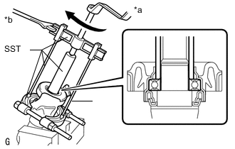
Text in Illustration *a Turn *b Hold Using SST, install the No. 1 center support bearing assembly.
- SST
- 09330-50010
- 09950-00020
- 09950-40011 ( 09951-04020, 09953-04030 )
- 09950-50013 ( 09952-05010, 09954-05080, 09955-05040 )
Note
Be sure to install the bearing in the correct direction.
-
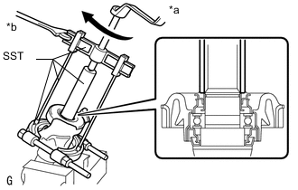
Text in Illustration *a Turn *b Hold Using SST, insert a new No. 2 propeller shaft dust deflector until it almost touches the rubber of the No. 1 center support bearing assembly.
- SST
- 09330-50010
- 09950-00020
- 09950-40011 ( 09951-04020, 09953-04030 )
- 09950-50013 ( 09952-05010, 09954-05080, 09955-05040 )
Note
Be careful not to damage the propeller shaft No. 2 dust deflector.
-
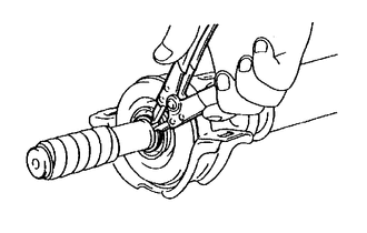
Using a snap ring expander, install a new No. 2 propeller shaft dust deflector snap ring.
-
-
INSTALL PROPELLER INTERMEDIATE SHAFT ASSEMBLY
-
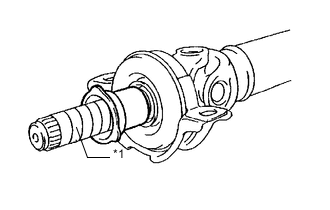
Text in Illustration *1 Protective Tape Install the dust boot.
Note
Assemble the propeller intermediate shaft assembly after wrapping protective tape around the spline so that it will not damage the boot.
-
Apply grease to the spline.
Grease Molybdenum disulphide lithium base NLGI No. 2 -
Install the adjusting nut to the propeller intermediate shaft assembly.
-
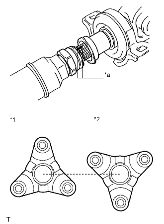
Text in Illustration *1 Propeller Intermediate Shaft Assembly *2 Propeller Shaft Assembly *a Matchmark Align the matchmarks and install the propeller intermediate shaft assembly to the propeller shaft assembly.
Note
The directions of the propeller intermediate shaft assembly companion flange and the propeller shaft assembly companion flange should differ by 180°.
-
Cover the adjusting nut with the dust boot.
-
Temporarily tighten the adjusting nut by hand.
-