SHIFT PADDLE SWITCH INSPECTION
PROCEDURE
-
INSPECT TRANSMISSION SHIFT SWITCH ASSEMBLY
-
Disconnect the No. 1 switch wire connector from the transmission shift switch assembly.
-
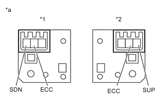
Text in Illustration *1 for LH ("-") *2 for RH ("+") *a Component without harness connected
(Shift Paddle Switch Assembly)
Measure the resistance between each terminal when the transmission shift switch assembly is moved to each position.
Standard Resistance Tester Connection Switch Condition Specified Condition SDN - ECC Pull continuously
"-"
(Down shift)
Below 2.5 Ω SDN - ECC Release
"-"
(Down shift)
1 MΩ or higher SUP - ECC Pull continuously
"+"
(Up shift)
Below 2.5 Ω SUP - ECC Release
"+"
(Up shift)
1 MΩ or higher If the resistance value is not as specified, replace the transmission shift switch assembly.
-
-
INSPECT NO. 1 SWITCH WIRE
-
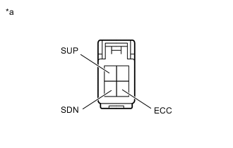
Text in Illustration *a No. 1 Switch Wire
(to Spiral Cable with Sensor Sub-assembly)
Connect the No. 1 switch wire connector to the transmission shift switch assembly.
-
Disconnect the steering pad switch connector from the No. 1 switch wire.
-
Measure the resistance between each terminal when the transmission shift switch assembly is moved to each position.
Standard Resistance Tester Connection Switch Condition Specified Condition SDN - ECC Pull continuously
"-"
(Down shift)
Below 2.5 Ω ↑ Release
"-"
(Down shift)
1 MΩ or higher SUP - ECC Pull continuously
"+"
(Up shift)
Below 2.5 Ω ↑ Release
"+"
(Up shift)
1 MΩ or higher If the resistance value is not as specified, replace the No. 1 switch wire.
-