SHIFT LEVER INSPECTION
PROCEDURE
-
INSPECT SHIFT LOCK CONTROL ECU SUB-ASSEMBLY
-
Check the shift lock operation.
-
Move the shift lever to P.
-
Turn the power switch off.
-
Check that the shift lever cannot be moved to any position other than P.
-
Turn the power switch on (IG), depress the brake pedal and check that the shift lever can be moved to the other positions.
If the operation cannot be done as specified, inspect the shift lock control unit.
-
-
Check the shift lock release button operation.
-
Using a screwdriver, remove the shift lock release cover.
-
When moving the shift lever with the shift lock release button pressed, check that the shift lever can be moved to any position other than P.
If the operation cannot be done as specified, check the shift lever assembly installation condition.
-
-
Check the key interlock operation.
-
Turn the power switch on (IG).
-
Depress the brake pedal and move the shift lever to any position other than P.
-
-

Text in Illustration *a Component with harness connected
(Shift Lock Control ECU)
Inspect the shift lock control unit assembly.
-
Measure the voltage according to the value(s) in the table below.
Tech Tips
Do not disconnect the shift lock control unit assembly connector.
Standard Voltage Tester Connection Condition Specified Condition 4 - 1 Brake pedal depressed 11 to 14 V ↑ Brake pedal released Below 1 V 5 - 1 Power switch on (IG) 11 to 14 V ↑ Power switch off Below 1 V If the voltage value is not as specified, replace the shift lock control unit assembly.
-
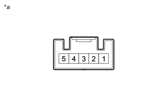
Text in Illustration *a Component with harness connected
(Shift Lock Control ECU)
Measure the resistance according to the value(s) in the table below.
Tech Tips
Do not disconnect the shift lock control unit assembly connector.
Standard Resistance Tester Connection Condition Specified Condition 1 - Body ground Always Below 1 Ω If the resistance value is not as specified, replace the shift lock control unit.
-
-
-
INSPECT TRANSMISSION CONTROL SWITCH
-
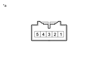
Text in Illustration *a Component without harness connected
(Transmission Control Switch)
Measure the resistance between each terminal of the transmission control switch when the shift lever is moved to each position.
Standard Resistance for LHD Tester Connection Condition Specified Condition 4 - 5 S, "+" and "-" Below 1 Ω ↑ Except S, "+" and "-" 10 kΩ or higher 3 - 2 Press continuously "+" (Up shift) Below 1 Ω ↑ S 10 kΩ or higher 1 - 2 Press continuously "-" (Down shift) Below 1 Ω ↑ S 10 kΩ or higher for RHD Tester Connection Condition Specified Condition 4 - 5 S, "+" and "-" Below 1 Ω ↑ Except S, "+" and "-" 10 kΩ or higher 1 - 2 Press continuously "+" (Up shift) Below 1 Ω ↑ S 10 kΩ or higher 3 - 2 Press continuously "-" (Down shift) Below 1 Ω ↑ S 10 kΩ or higher If the resistance value is not as specified, replace the transmission control switch.
-