SHIFT LEVER POSITION SENSOR INSTALLATION
PROCEDURE
-
INSTALL SHIFT LEVER POSITION SENSOR
-
Install the shift lever position sensor to the hybrid vehicle transmission assembly.
Tech Tips
Make sure that the manual valve lever shaft has not been rotated prior to installing the park/neutral position switch as the detent spring may become detached from the manual valve lever shaft.
-
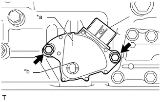
Text in Illustration *a Neutral Alignment Mark Line *b Groove Temporarily install the 2 bolts.
Tech Tips
Tighten the bolts with the neutral alignment mark line aligned with the groove. [*1]
-
Install a lock washer and the nut.
- Torque:
- 6.9 N*m { 70 kgf*cm, 61 in.*lbf }
-
Temporarily install the control shaft lever.
Tech Tips
Stake the claws of the nut stopper before fully tightening the nut. [*2]
-
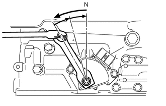
Turn the control shaft lever counterclockwise until it stops. Next, turn the control shaft lever clockwise 2 notches to set it to N.
-
Remove the transmission control shaft lever.
-
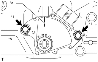
Text in Illustration *1 Adjusting Bolt *a Neutral Alignment Mark Line *b Groove Align the neutral alignment mark line with the switch groove, and tighten the 2 adjusting bolts. [*1]
- Torque:
- 5.4 N*m { 55 kgf*cm, 48 in.*lbf }
-
Using a screwdriver, bend the lock washer tabs to secure the nut.
Note
Make sure that the nut is held firmly.
-
Install the transmission control shaft lever with the nut. [*2]
- Torque:
- 16 N*m { 160 kgf*cm, 12 ft.*lbf }
-
Connect the shift lever position sensor connector.
-
-
INSTALL REAR ENGINE MOUNTING MEMBER
-
Tilt up the hybrid vehicle transmission assembly.
-
Install the rear engine mounting member to the body with the 4 bolts.
- Torque:
- 35 N*m { 354 kgf*cm, 26 ft.*lbf }
-
-
CONNECT FLOOR SHIFT GEAR SHIFTING ROD SUB-ASSEMBLY
-
INSTALL PROPELLER WITH CENTER BEARING SHAFT ASSEMBLY
-
INSTALL INTAKE AIR SURGE TANK ASSEMBLY
-
INSPECT SHIFT LEVER POSITION
-
ADJUST SHIFT LEVER POSITION
-
INSPECT SHIFT LEVER OPERATION
-
INSTALL NO. 2 ENGINE UNDER COVER
-
INSTALL FRONT SUSPENSION MEMBER BRACE